What modifications did you have to make to Rogic's output stage? I'd definitely like to give it a try with the AD1862. 🙂
Do you mean this?
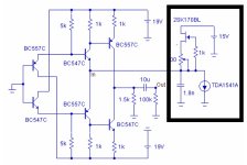
Yes, thats the one. The modifications were:
2k7 for the IV resistor instead of 1k5 (well mine has 2k5 rhopoints, but use what is right for you)
You don't need any of the parts around the 2sk170 which compensates for the V offset of the TDA1541 I believe.
I got away without needing an output cap, one less cap in the chain by putting a bit of heatshrink around the transistors, filling it with thermal paste and heatshrinking it down to get reasonable thermal coupling.
I'm feeding it +/- 20V.
If you use different transistors, then you will need to verify pinout if they are different.
FYI - that board is quite big, and this IV stage could be made a lot smaller/compact if thats important to anyone.
This is one of the great joys of this design - there are lots of opportunities to try different output stages - solid state and valve based. A favourite among a few friends here is the cheap 6n2 SRPP module from aliexpress. 30e for the fully built stage, another 20e for the r-core transformer, and you have a ready to go valve output stage. I've done a couple with a 3a5 DHT stage as well (excellent but complicated build), also Patricks current mirror and Sen.
Last edited:
in this paper the clever Thorsten Loesch gave also a simple shematic without expensive traffos for different PCM dac chip like the one we discuss in this thread. This is the revised issue.
The 2 uF output cap to save from a OT can be lowered according the input impedance of your preamp/amp. 0.47 uF for 50k input for instance. Permit to choose a good film cap enough ( SCR KP Sn, Mundorf Supreme, Copper foil...)
The 2 uF output cap to save from a OT can be lowered according the input impedance of your preamp/amp. 0.47 uF for 50k input for instance. Permit to choose a good film cap enough ( SCR KP Sn, Mundorf Supreme, Copper foil...)
Attachments

You don't need any of the parts around the 2sk170 which compensates for the V offset of the TDA1541 I believe.
woodturner-fran,
Thank you for the information on the Pedja Rogic
Discrete Diamond Non-Feedback I/V Stage. I’m going to give this buffer a try. Already ordered the board and a bunch of the BC557C and BC557Cs.
So I don’t need the components in the box in the attached picture for the AD1862?
Attachments
I am wandering if anyone looking for good resistor,
please come here for group buy
Precision Resistor GB? General Resistance (Rhopoint) GG102
please come here for group buy
Precision Resistor GB? General Resistance (Rhopoint) GG102
@tamra, I signed up right away. Hopefully there will be more interest.
I would like to realize this dac in two chassis.
PSU in one chassis, with toroid + rectifier + caps. DAC with jls board and i/v stage in the other.
have not yet decided how I want to implement the power supply. I have a leftover toroid 2x21v, two super regulators and a 5v salas shunt.
I thought to use the regs +-12v/+-5v for the DAC, the shunt for the JLS board +5v. But think it's a bit too complicated if I want to add a discrete I/V stage later.
what do you all think? too complicated? use something else?
Or maybe it would be possible to have the board of the psu 2 in two parts? @miro
...just for the sake of simplicity😀
cheers,
jules
no problem
Hi,
The reg board must be near the load with the PSU2 and very low noise modern reg chips. However it's less important if you use 78/79xx simple 3 legs regs that can be farer as you can see in some old DAC (remember we said it likes some Z at their output.).
If for some reason you want to use two chassis, then in the PSU chasis you should just put the power traffos and in the DAC chassis, the rectifiers, smoothing caps and regs. Try to make short wire connection between the two box, i.e. between the secondaries of the power traffo and the rectifier bridge : à la Naim with short wire between the two box wires connectors.
Try also R-Core transformer for a smoother result.
My two cents, maybe Miro has another vision though.
You also should use shielded wires between the two boxs and respect box grounding security, i.e. earthing to the main.
Last edited:
Thanks for asking about separate PSU, jules. I'm going to do the same and didn't think about the implications.
I'll do another resistor buy if there's interest, need another 20 or so resistors though so be sure to update the other thread if interested.
I'll do another resistor buy if there's interest, need another 20 or so resistors though so be sure to update the other thread if interested.
I edited the post about security issues (grounding : earthing is a more correct word, i.e. connect the metal chassis to the Earth and also the second chassis to the first via the conectors through the linking wire)
I thought it would be better/safer to only send unregulated dc between the two chassis instead of ac.
And as you wrote diyiggy, the regs then directly next to the dac with short connections.
I was thinking of the Pearl 2 preamp.
But maybe that's not ideal for the dac at all...
Thanks for the input regarding grounding, haven't thought about it yet.
And as you wrote diyiggy, the regs then directly next to the dac with short connections.
I was thinking of the Pearl 2 preamp.
But maybe that's not ideal for the dac at all...
Thanks for the input regarding grounding, haven't thought about it yet.
Yes you can do that, keep the after smoothing cap link between the two box as short as possible, you also can profite of that to make a Pi filtering connection with an Input DC reservoire cap in the second dac device after the main smoothing cap in the first power box with for instance a 1R 2W carbon resistor. but don't forget if you use the PSU2 reg of this thread it is an AC input !
But there is no substantial advantage of such an architecture layout imo with modern reg chip and designs. More a need if you have headroom for vertical stacking instead room for horiziontal standalone chassis.
But there is no substantial advantage of such an architecture layout imo with modern reg chip and designs. More a need if you have headroom for vertical stacking instead room for horiziontal standalone chassis.
Last edited:
Many thanks for the valuable inputs.
The idea with the two chassis came about because i want to stack the dac on the pearl 2.
You mean something like this with the pi-filter (like a crc filter):
Box 1
toroid, rectifier, caps, resistor 1r 2w
short link
Box 2
caps, regs, dac
I definitely need to read more about the pi-filter.
The idea with the two chassis came about because i want to stack the dac on the pearl 2.
You mean something like this with the pi-filter (like a crc filter):
Box 1
toroid, rectifier, caps, resistor 1r 2w
short link
Box 2
caps, regs, dac
I definitely need to read more about the pi-filter.
A Pi filter is a CRC or CLC (better) and they can be chained in serie, the main idea is to smooth the AC ripple. You will find a ton of ressource as calculator like PSUD2
An illustration of a symetric Pi filter for a +/gnd/- can be seen in the PSU2 board of this thread, see first post for the link.
An illustration of a symetric Pi filter for a +/gnd/- can be seen in the PSU2 board of this thread, see first post for the link.
Last edited:
woodturner-fran,
Thank you for the information on the Pedja Rogic
Discrete Diamond Non-Feedback I/V Stage. I’m going to give this buffer a try. Already ordered the board and a bunch of the BC557C and BC557Cs.
So I don’t need the components in the box in the attached picture for the AD1862?
Diyiggy got there before me - yes, its useful because you don't need the hardest to find part, the 2sk170. When you power up, let it settle for a little and check for DC offset - if matching and thermal contact is good then you won't need the output cap.
woodturner-fran,
I should have enough of the BC557C and BC557Cs (100 each) to make quite a few matching sets. They are cheap enough that it made sense to order a lot of them.
I should have enough of the BC557C and BC557Cs (100 each) to make quite a few matching sets. They are cheap enough that it made sense to order a lot of them.
@tubee
I bet it is something with the RPI strimmer (settings?) ... glue logic does one thing: divides the left and right channels using buffer, and if the streamer sends mono, than the mono will be played, if it sends stereo, than the stereo will be played 🙂
Thanks Miro. I will check settings in rpi, maybe time to try moode or so to solve that.
- Home
- Source & Line
- Digital Line Level
- DAC AD1862: Almost THT, I2S input, NOS, R-2R