Hi Andrew,
Thanks. Yes, two dead channels for sure unless special precautions are taken. Don't do it Ciu.
These amps are best used as they were intended.
-Chris
Thanks. Yes, two dead channels for sure unless special precautions are taken. Don't do it Ciu.
These amps are best used as they were intended.
-Chris
Hi everyone,
Just replaced the supply caps tonight. Swapped the original 10000uF 50V Elna for 12000uF Nichicon LK 63V. Got a cheap deal on Ebay.
Late night first impressions are favourable.
The bass seems to go deeper now. I'm trying to avoid the stereophile descriptions ........ must resist ...... temptation...... to ..... say that ....... bass ... is..... 'blooming'. 😀
I'll comment further in the morning when I can play it louder.
This an experiment to see whether it is worth recapping the PSX that I normally use. Quality caps for that will be expensive.
Cheers,
Martin.
The Stick Insect Breeding Company
(Formerly known as Mouse Multipliers International)
After listening at decent levels........
Yep, Definite improvement with the new caps.
Not mind blowing but definitely noticeable. As I said last night, more bass and it reaches lower which helps to offset the forward nature of my setup.
In my opinion, the rest of the frequency range is largely unaffected. It may be different for you if your C2 originally had Slit foil caps fitted.
I would definitely say that new caps in the Cyrus 2 (alone) make it sound better than it does with the PSX and it's original caps.
The next experiment is to find whether new caps in the PSX give a similar improvement?
An important message here is that a second hand PSX is probably not a fantastic bargain when you consider that you would have to replace those large (4) 15000uF caps before you improve upon a Cyrus Two with 2 new relatively inexpensive caps.
Having said that I'm still glad that I have a PSX despite the £60 or more it may cost me to replace it's caps.
Please remember that all of the above is simply my opinion based on my experiences with my setup and my particular capacitors.
I'm a little bit sceptical about cap 'break-in' so it'll be interesting to see if things change over time.
Cheers,
Martian. 🙂
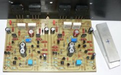
Cyrus 2 with blown cap and trace
I have a cyrus 2 ..according to posts on this site looks like I have issue 6 design (i.e pushbutton mains switch).
Had cap 470uF 50V blow (not explode) and also trace burnt off board same as "atomised".
ALso had blown op amps in MC and MM sections of the PCB
From reading the posts on the site I replaced both
C63, C64 with a 470uF 100V
I made good the burnt out trace.
I replaced the 2 regulators with new LM317 and LM 337.
I removed but did not replace the blown amplifiers in the MC and MM sections of the PCB as I only wasnt to Play CDs dont mind if truntable circuitry is isolated altogether
I power the amp up and it worked for a couple of hours.
BUt then I notivced that volume decreased and had tearing sound on lhs.
Any suggestions..what diodes to check..any chance of rev 6 cyrus schematic ?
thanks in advance for any help.
Sean
Hi there, I am a totally ignorant person on technical matters. I have trouble with my Cyrus 2 amp. One channel drives only the tweeter, it no longer drives the midrange or woofer. I have brought it to my technician who explained to me he needs a schematic. I have found one for Cyrus 1 on this site. I also read that another user has had a similar problem....one channel was giving him 1/5 of the output. Can anyone help me.
Excuse me in advance for my poor technical language in trying to explain my problem. Hope someone is out there!!!Thanks for your attention
Excuse me in advance for my poor technical language in trying to explain my problem. Hope someone is out there!!!Thanks for your attention
clappy said:....... I have brought it to my technician who explained to me he needs a schematic. .......
Have you showed your technician the Cyrus 1 schematic? It's similar enough to be useful.
Thanks for the speedy reply... no I have not given it (the schematic) to him. Hope to next week. Just wondering whether anyone can suggest where to look, so as not to have to check every detail, step by step.
By the way how much would you pay for a 2nd hand Cyrus 2, well kept, being sold on Ebay by a person who due to hearing problems is no longer able to enjoy listening or rather hearing the finesses of good music. The sale ends tomorrow and at the moment the bid is around the 120Euros.
Thanks again for your help
Why not search Ebay yourself? Have a look at ended listings.clappy said:By the way how much would you pay for a 2nd hand Cyrus 2, well kept, being sold on Ebay by a person who due to hearing problems is no longer able to enjoy listening or rather hearing the finesses of good music. The sale ends tomorrow and at the moment the bid is around the 120Euros.
Thanks again for your help
I would say from memory that 120 euros is the upper limit. What's it worth to you?
Some do go for more but this seems to be a random event. Newer models go for more. ......... unless it's a 'rare' early model where all of the paint has rubbed off the dials and the seller 'thinks' it's a special edition. 😀
*EDIT*
Hey, what do I know? A very good condition Cyrus one just sold for £107. !!
Please folks, do you have the layout to help me to build this Cyrus one
Here is the board.
Some layout with transparence (Ray X) will be interesting...or, position of parts and component values over the board.
Of course i can discover that by myself...but will be a hard work and will waste a lot of time doing that.
Help!
Carlos
Here is the board.
Some layout with transparence (Ray X) will be interesting...or, position of parts and component values over the board.
Of course i can discover that by myself...but will be a hard work and will waste a lot of time doing that.
Help!
Carlos
Attachments
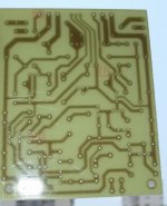
That is not an actual Cyrus board. Did you know there was a Cyrus clone thread on here? Maybe the board is from that. The thread had all details for building on 🙂
edit: what a good guess - that is indeed the clone board.
http://www.diyaudio.com/forums/showthread.php?s=&threadid=95021&highlight=
edit: what a good guess - that is indeed the clone board.
http://www.diyaudio.com/forums/showthread.php?s=&threadid=95021&highlight=
I have already found the informations i need.
Thank you folks.
Do not know if clone or not clone.
This board you see was assembled by my friend Klaas Veenstra...do not remember exactly..but i think he has made the board and have sent me.
So... seems to me you do not have the layout...sorry folks.
I already have the layout from Klaas... this was made a long time ago... i forgot.... i am quite sure he has made the layout by himself and ordered boards in Nederland.
regards,
Carlos
Attachments
Layout was made by Geoff , Carlos.
It was in the Cyrus 1 project thread Richie00boy linked to.
I had two extra made and sent it to you because you mentioned wanting to try the cyrus again with these boards.
Best regards,
Klaas
It was in the Cyrus 1 project thread Richie00boy linked to.
I had two extra made and sent it to you because you mentioned wanting to try the cyrus again with these boards.
Best regards,
Klaas
Hi there,
nice thread, very useful !
I have a Cyrus 2, push-button-version, Headphone socket left side as seen from front. It is nearly 20 years-old. Since some days I notice a humming sound, increasing when turning up the volume. I listen only with the Phono stage. I notice that the "hum" is louder when the amp is switched off for a while, so I keep it turned on. When listening to records you can hardly hear the "hum", but by just turning the volume knob the strange sound becomes loud. I already switched to another high-level input, e.g. CD, AUX, etc. with the result that there is no "humming" sound. Could it be that one or more capacitors in the phono stage ( C71,C72) are aged ? I checked the cpacaitors C67 and C68, they are already 63V, 470uF types, the other capacitors don´t look "exploded" or otherwise stramge either.
Thanks for some comments on this specific problems !
Best regards
Rad
Hi Rad,
Best to turn your amp off when not in use. It needs service, simple as that. Can you measure the capacitors? I would simply replace them all with new. Once done that, check the main filter caps with your 'scope. The waveform trumps measurements most days.
Hi clappy,
The same schematic is used for both models. Your problem is pretty easy to figure out though. The answer is jumping right out at your technician. The feedback to ground capacitors are opening up. Replace both. They are the two larger ones under the flat ribbon cable. Stunningly simple to figure out.
Hi Sean,
The low voltage supply is only used for phono. May as well remove your new caps and regulators. Pull the LV diode bridge will you are at it. Understand that the phono section on these is very good. Keep those parts you pulled, some are pricey to replace.
What probably happened was the regulators were oscillating due to the open 22 uF bypass capacitors. The op amps may have survived, you never know. Keep the older parts. You didn't have to use different regulators in here either. To be honest with you, the originals were a fine choice, but they did require replacement. Did you use thermal compound on the clip on heat sinks? Not that it matters anymore now.
One last thing I want to say about these. They were very well engineered. Better than average for sure, so don't modify these without using a great amount of thought. I doubt you are going to do a better job than the original designer did. As for your other problems, replace the other capacitors in the amplifier circuits. That should settle the amplifier down.
Let us know how you all do please.
-Chris
Hi Chris,
thanks a lot for your fast answer. Since I don´t own a "scope" but assume that the main caps are dry after nearly 20 years of use, I would like to replace them as well. I noticed that I also have the ELNA 50V, 10.000 uF, 50°C type. They measure a length of 60 mm and a diameter of 35 mm. Any clue what type to solder in instead ? Can I use 63V and more capacity types as well ? I only found caps with a length of 50 mm. Any ideas ? I´m sure you have ! ;-)
I also need replacement for one of the 5W triple-leg High-Watt resistors (RGC 33 Noble)@ R108. Any replacement type known ?
Thanks again for a fast answer !
Best regards
Rad
Hi,
I'd try to stay close to the original capacitance for the main psu-caps to avoid increased stress on the rectifier/ increased psu-noise.
Higher working-voltage isn't a problem, try to get some quality (slitfoil ?) caps that fit.
After 20 years of use the amp would probably benefit from replacing all electrolyts, the amp is worth it.
Why do you think one of the dual emitter-resistors need changing ?
Best regards,
Klaas
Hi,
I´d like to know how to replace the ELNA capacitors of light orange colour 50V, 1uF and 50V, 2.2uF @ C5, C6, C31,C32, C37, C38, C17, C18, C23, C23, C24, C25, C26. I don´t see any polarity sign on the PCB for these types. They are labeled CE-BP. Stands for Bipolar ? Doesn´t matter the direction of soldering in ? Any ideas ?
I managed to replace the two main capacitors against 63V, 10.000uF Slitfoils.
Does anyone have an idea whether it makes sense to replace C11, C12, C27 which are green WIMA foil capacitors with a tolerance of 10% against WIMA´s with 2.5 % tolerance ? Is there any problem not to do so ?
Thanks again for a fast answer from someone !
Best regards
Rad
- Status
- Not open for further replies.
- Home
- Amplifiers
- Solid State
- cyrus 2