A square fit it will be 😉.ekd said:[B...Maybe think of it this way... Design and cut your parts as if you were going to glue them together. If they fit squarely together the fastener's holes will not have to be so precisely sized/positioned. Make them fairly precise, and you will enjoy easy assembly (and it will make you proud when putting in a couple of screws.. and suddenly all the other holes line right up). As you develop your skills, you will find that making the really small stuff is not as hard as it used to be....[/B]
Hehe, thanks 🙂ekd said:The vents look nice. And the drawing is superb. and...
If anyone asks what you did over the summer, you will have something nicer to show them than a bail receipt or an STD...
You won't have time to get into trouble... 🙂
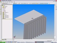
Ok, if I find the time I'll model simple holes this evening. It would indeed be a lot easier 🙂.ekd said:D, if you simply drill holes, where pic indicates, you will open up the heat trap formed in the corner. It'll vent completely, and take very little time.
When form follows function, the piece will naturally look good. And the precision of the holes (that don't need hand finishing) will look better than anything you can do without a mill (one crooked vent, and it is all you will see when you look at the top. Trust me, even if no one else notices...).
Maybe draw it up, and consider it? Or, put half as many bigger holes, centered on every other fin... Polish the fin, and give us all something to look at inside the hole?
It's a chasis for a class A 🙂. If my calculations are correct there will be +-160 watt for each side, since the output is 30 watt, that's 130 watt turned into heat 😀.Brian Donaldson said:Or cut it to hang 1/4" or so over the base of the heatsink and file a pretty chamfer on the edge. Anything covering the edge will impeed natural convetion and the "chimney effect". But it really won't matter unless this chasis is for Class A. If so, every little bit counts.
I don't find it all that pretty when the panels are not overlapping the heatsinks. Wouldn't the panels make up a bit for the loss of cooling of the heatsinks? I guess they'll absorb some of the heat too.
Ok, so the vent slots are a bad idea unless I've got access to a mill. Well, I got access to a mill 😀. Although I'm not sure if it's big enough for a 30cm x 19" panel. It's a small mill/lathe combination kind of thing. If the panel doesn't fit under it, I won't try to make those vents. Promise 😉.chipco3434 said:Devil!
Stop Now!
OK everything you've been told is true ~ from Peter regarding convection and from Ed on drilling.
But...
Don't do those slots. They will be VERY difficult to get correct. You can always take it apart and do them later if's a Class A room heater. The difficulty on slots is that the tool wants to move one way or the other so the slots look like big "commas" to the eye. The eye can easily discern a distorted pattern in the range of ~.2 or .3 mm. Also, every time you cut a hole it needs to be deburred or chamfered, each step is a possibility for a mistake.
Next item...
Hole clearance~ there are two standards here in the USA, "close fit" and "free fit". There is surely something like close and free in metricville.
In round numbers, close and free are 3% and 6% (respectively) over the nominal fastener size. So a close fit on a 6mm fastener would be 6mm +(3%*6mm)=6.18 mm ~ 6.15 mm. A free fit would be about 6.35 mm. Forget about getting a 6mm fastener into a 5.5mm hole. You would need a BIG HAMMER!
Drilling holes. There is no way to get a hole in position without giving it some method of starting in that position. Without a little help, the drill moves .5mm to the side and then starts downward. BAD!
There are three ways of getting the drill not to "walk" (move laterally before "digging in").
1. Punch the hole location with a sharp object leaving a small crater that the drill will not walk out of.
2. Use a "center drill". This is a drill with a very shallow included angle on the tip that prevents it from moveing laterally. It is only meant to drill 2-3 mm deep. It is used to start a standard twist drill.
3. Use a drill with some sort of "special" point geometry... a split point drill. This is a drill where the chisel point is ground to eliminate the typical flat spot on a the drill tip.
In most cases, all that is needed is a healthy whack of a hammer on a sharpened punch to produce a spot where the drill will start and not go sideways. This is even necessary when drilling on a rigid press or mill if you are using a conventional drill point. The drill will certainly move outside the boundries that we have established for a "close fit" and perhaps even a "free fit".
If you have the holes in the panels, we would typically use a thing called a "transfer punch" to mark the spots for drilling on the heatsinks. The transfer punch is the diameter of the drilled hole in the panel.... very close fit ~.1mm, and it has a sharp point on the end. You put the punch through the hole of the panel, touching the heatsink. Hit it with a hammer and it will leave a small mark on the heatsink where the next hole may be drilled and then tapped....
I was certainly going to use a punch to mark the hole location. Then I'd drill all holes with a 1mm drill and work my way up 'till I reach the final width. I'll look into center & split point drills.
A transfer punch looks interesting. I'll check that out too 🙂.
You're certainly right about that. I drilled the holes for the TO-3's with a drill press and it was pretty hard. Some holes aren't straight at all. But of course, that's a bit my own stupid fault. Stupid things I did: holding the heatsinks by hand, using an old drill (didn't notice it untill it was already too late), not parking the hole alignments in the most precise way (the paper I had for the TO-3 holes layout was kind of lousy).chris ma said:From Devil's drawing I think he may have a hard time to use a drill press on that heatsink. I had similiar situation before either the chunk is too big that it gets in the way or needing a very very long drill bit and hope it does not do the walking. The most challenging task that he will face I would think is the precision of all the holes alignments. With each increasing mm in length of the stand off the more precise each has to be. And there are 24 holes. That means out of 12 holes if 1 is missed then that side is some what ruined. A tough task and very high standard he is aiming for. I wish him best of luck.
Still, I can imagine that even if done well it will be quite hard. Have you or any one else got any tips for this?
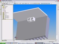
I know that's the easiest solution, but I don't like the looks 🙄. Nice render! I guess I have to check out Solidworks 🙂.baggystevo82 said:Here's what I would do, should look nice and tidy and allow the best aairflow over the heatsink...
SC
"How can I hold the panels in place, and use it as guide to drill an accurate hole that will make the chassis more even? "
One way to do it is to accurately scribe and drill the panel, and confirm the measurements. Then do the same for the mating surface's first hole. Attach them, and use the panel to guide the center punching (or c-drilling) of the second hole. Disassemble and drill second hole. Assemble and c-punch the rest. Drill away.
Using any part as a drill guide will ensure the "egging" of the holes, and ruin all precision (use parts only as punch guides). Real drill guides are hardened beyond any possibility of this. And using transfer punches makes it quick, but if you don't have 'em, just take a look at each punch mark to assure that they are centered in the hole... Take the time to insure this...punch as many light marks as it takes to get it right, then set the the mark firmly.
Isn't it about time that everyone get themselves a cheap dial caliper? I'd be lost without mine, and any real precision must begin with accurate measurement...
DH... Ain't nuttin' gonna stop you now! 🙂 I'd like to see how the "reveal" style holes would look.
E
Re: SC
If I'm able to email myself the model file this evening (I'm at my father's, file is on my PC at my mother's house), I'll try the reveal thing 🙂.
Ok, thanks a lot for those tips!ekd said:[B....
DH... Ain't nuttin' gonna stop you now! 🙂 I'd like to see how the "reveal" style holes would look.[/B]
If I'm able to email myself the model file this evening (I'm at my father's, file is on my PC at my mother's house), I'll try the reveal thing 🙂.
D,
One way I would do it if I have to cover the fins with the top and bottom panels. Cut a piece of solid wood/mdf the same/precise dimension between the transistor extrusion and the top plate. Clamp the top plate between the bottom of the extrusion and the top surface of the top panel with the wood inside. Use a long bit that is long enough to go thru the top panel wood and the extrusion in one go. Must mark and centre punch the holes on the top panel first. Drill press is a must and secure the stock firmly.
Chris
Chris,
Did you ever find the trace tape you needed? I tried the "glass amp" concept that you put in my head...Looks pretty cool. May make one someday, it had a nice mix of "artsy" and tech.
If you like, I could send you 10 ft of the stuff (more if you need).
E
Did you ever find the trace tape you needed? I tried the "glass amp" concept that you put in my head...Looks pretty cool. May make one someday, it had a nice mix of "artsy" and tech.
If you like, I could send you 10 ft of the stuff (more if you need).
E
Hm, good idea! I'd need a pretty long drill though. Another thing on my to-search-for list 🙂.chris ma said:...One way I would do it if I have to cover the fins with the top and bottom panels. Cut a piece of solid wood/mdf the same/precise dimension between the transistor extrusion and the top plate. ...
Ekd,
Thanks for the offer. Yes I bought some tapes and there was some adhesive backed copper sheet of 12" X 12" too. Yet to use them..hopefully soon.
Chris.
Thanks for the offer. Yes I bought some tapes and there was some adhesive backed copper sheet of 12" X 12" too. Yet to use them..hopefully soon.
Chris.
And...
Just poured a sheilded version of the PSU (foil) to compare, and was wondering if I should have stripped a length of the ground wire, from the supply cord, and wrapped it into the shield?
E
Just poured a sheilded version of the PSU (foil) to compare, and was wondering if I should have stripped a length of the ground wire, from the supply cord, and wrapped it into the shield?
E
Re: SC
Thx I will try to take my time and try that out.
ekd said:"How can I hold the panels in place, and use it as guide to drill an accurate hole that will make the chassis more even? "
One way to do it is to accurately scribe and drill the panel, and confirm the measurements. Then do the same for the mating surface's first hole. Attach them, and use the panel to guide the center punching (or c-drilling) of the second hole. Disassemble and drill second hole. Assemble and c-punch the rest. Drill away.
Using any part as a drill guide will ensure the "egging" of the holes, and ruin all precision (use parts only as punch guides). Real drill guides are hardened beyond any possibility of this. And using transfer punches makes it quick, but if you don't have 'em, just take a look at each punch mark to assure that they are centered in the hole... Take the time to insure this...punch as many light marks as it takes to get it right, then set the the mark firmly.
Isn't it about time that everyone get themselves a cheap dial caliper? I'd be lost without mine, and any real precision must begin with accurate measurement...
DH... Ain't nuttin' gonna stop you now! 🙂 I'd like to see how the "reveal" style holes would look.
E
Thx I will try to take my time and try that out.
Re: Anybody know...
No. The best DIY technique is to run a conductive band around the exterior. This is a somewhat effective magnetic shield because it acts like a shorted turn for the leakage inductance.
Surrounding the unit with a grounded conductive material will stop some RFI, probably not worth it IMHO. I also have not been impressed by attempts at using mumetal or steel for magnetic shielding.
ekd said:If static proof bags would make an EMF shield for transformers?
E
No. The best DIY technique is to run a conductive band around the exterior. This is a somewhat effective magnetic shield because it acts like a shorted turn for the leakage inductance.
Surrounding the unit with a grounded conductive material will stop some RFI, probably not worth it IMHO. I also have not been impressed by attempts at using mumetal or steel for magnetic shielding.
SC, pick your first holes carefully (this will make sense when it's in your hands) and check the first two in all ways possible, and the rest is too easy. 🙂
T, did you run into any easy ways to color Bondo?
First finished Transpot shown, simple pretty much says it...
E
T, did you run into any easy ways to color Bondo?
First finished Transpot shown, simple pretty much says it...
E
Attachments

That is clean. I had already drilled my panel long long time ago but the angles just a pain. I will try that out as soon as I get to a shop.
ekd,
Nice work, looks professional. 🙂 No tips on coloring Bondo I am afraid.
Is it silent? I had a trannie that was in my Energy sub that went bad, drove me crazy so I removed it. I may have time to pot it this weekend and see how effective it is...if it fixes it, I'm sold. 😉 That 60Hz mechanical noise is a bear to damp.
Thanks, guys!
Don't know how it sounds yet... The paint is 7 (double,wet) coats of enamel (blocked between each). If I want to keep the shine, I can't touch it much for a week or so.
The shielded one is dead silent. You can feel it, though.
Ugly first one is still tickin'.
It will all be a matter of proportion, I'm guessing. Maybe you should pot that rattler in a bucket? 🙂
E
I just realized that the quickest, cheapest way to do this would be to scoop out some of a can of Bondo, mix in some hardener, and plop in a trans with terminals on it (leave some space for other guts?).
Hideously cost effective, shielded, and you wouldn't even get your hands dirty. It don't seem fair...
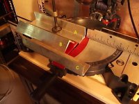
Definately A.
Support for both planes.
B allows the clamping forces to flex the part, and relies on structural strength to maintain the clamping force. I wouldn't try it with anything at all flexible.
C is Ok but might vibrate a bit (not as clean an edge left on the cut). I'd put a block of something under the clamp, supporting the upright against the pulling of the blade.
Brand of saw?
E
Thanks Ekd,
The saw is here http://www.diyaudio.com/forums/showthread.php?postid=403345#post403345
Chris
The saw is here http://www.diyaudio.com/forums/showthread.php?postid=403345#post403345
Chris
- Status
- Not open for further replies.
- Home
- General Interest
- Everything Else
- Cutting, drilling, mounting etc. for the absolute beginner