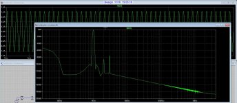
10X fqp3n30 have lower input capacitance than only one IRFP150N but better transconductance, so the result is not the same.
simulation shows in the performance of the amp, lower distortion, lower current on driver at high frequency
Yes, I've measured a few samples, actual values in this thread. Matching is pretty good out of the tube also.
Assorted Pulsed transistor measurements
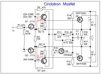

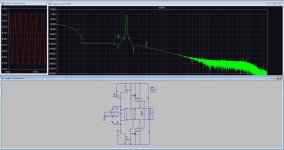
I bump into Joe Berry's latest schematics by chance, and find it quite interesting :
https://www.diyaudio.com/community/threads/joe-berrys-circlotron.384070/post-6974724
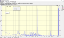
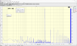
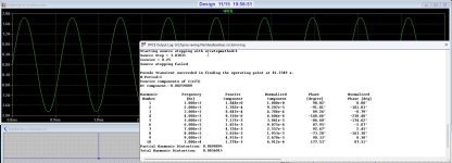
After taking some time to understand how it works, I was not entirely happy with the high H3 in the simulation.
So I tried a few things, including using all Toshiba active devices, and rich Class A bias.
The improvement is not insignificant.
Only simulations of course.
Best Regards,
Patrick
.
https://www.diyaudio.com/community/threads/joe-berrys-circlotron.384070/post-6974724
After taking some time to understand how it works, I was not entirely happy with the high H3 in the simulation.
So I tried a few things, including using all Toshiba active devices, and rich Class A bias.
The improvement is not insignificant.
Only simulations of course.
Best Regards,
Patrick
.
Attachments
Hey, Guys! Please make a specification sheet for the amplifier that we are discussing, all the ratings of the parts are contradictory. Or please lay out the final scheme..
Last edited:
I was busy with one, and another class D.
However circumstances did now allow me to go on, but Now I can go further, things
are fine now.
The classic rover P6 did need so much attentions, but it is almost done.
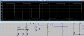
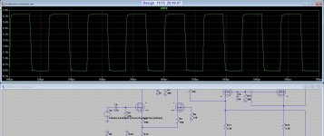
This is also a circlotron without feedback, a little different.
and one with feedback, who is very low hd.
However circumstances did now allow me to go on, but Now I can go further, things
are fine now.
The classic rover P6 did need so much attentions, but it is almost done.
This is also a circlotron without feedback, a little different.
and one with feedback, who is very low hd.
Attachments
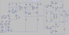
Our circuit is simpler and already works. At first there were mosfets in the output stage, but now we have settled on SIT transistors.This is also a circlotron without feedback, a little different.


Last edited:
- Home
- Amplifiers
- Solid State
- Current feedback Mosfet Circlotron