10X fqp3n30
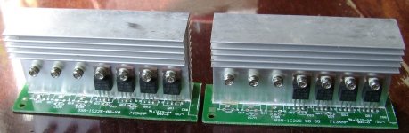
I found 8 pieces of IRF740. I put 4 + 4 at the output and measure Rout.
Attachments
Nice thread! I am preparing to build with VFETs. Power supplies independent from front.
no feedback
no feedback
Hi Joe Berry, Sebastien!!!FYI, some new simulation results using Micro-Cap 12 (free download here). All results are with input stage driven unbalanced.
I switched the circuit to an unbalanced input. It's okay. The amplifier output has symmetrical clipping.
Later Yura will measure the harmonic spectrum, and I will listen to how the amplifier sounds after changing the circuit.
Attachments
Thanks Eugene, that's good to know. Please share your impressions on the sound when you have a chance to listen to it.
Just a simulation test but good performance without global feedback
10X fqp3n30 have lower input capacitance than only one IRFP150N
I have an idea about auto-bias that eliminates the need of thermal tracking. I'm not sure if I can discuss it here.
Last edited:
Auto bias circuit
William Chater's "Bias control for power amplifiers," Revisited - diyAudio
William Chater's "Bias control for power amplifiers," Revisited
William Chater's "Bias control for power amplifiers," Revisited - diyAudio
William Chater's "Bias control for power amplifiers," Revisited
I checked the SOA of the IRFP150 in this Circlotron and it's just set to a safe limit. In the picture from the left to the right line: 8Ohms DC load, 4Ohms DC load, 8Ohms inductive load (reactance 5.6Ohms), 4Ohms inductive load (reactance 2.83Ohms). The curve is the DC SOA limit of the IRFP150 which does not intersect any load line. Cool
B+ 35V and device Max Power dissipation 230W. VDS max 100V just ok, higher would be safer.
B+ 35V and device Max Power dissipation 230W. VDS max 100V just ok, higher would be safer.
Attachments

Last edited:
I have an idea about auto-bias that eliminates the need of thermal tracking. I'm not sure if I can discuss it here.
HI
you have a PM
Class i Circlotron
Hello,
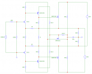
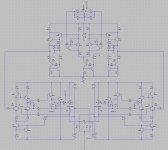
I attached the picture of the Class i circlotron power stage which I am willing to develop. My target is a 200W Circlotron.
Some good points:
It features auto bias where the output devices never switch off (Thorens TEM 3200) and lands to around 269ma according to the sensor resistor value of 0.2ohms. This avoid switching crossover distortion.
It does not double GM as in heavily biased power stages.
You can swap the output devices Q10 and Q20 with mosfet (enhanced) npn BJT or IGBT without changing values in the circuit.
It doesn't need thermal tracking of the output devices.
It requires low impedance drive.
I currently got it working in my lab but I need to develop it with a voltage stage.
I am simulating it with your voltage stage (second picture) as an idea.
If you like the idea we could open a new thread "Class i Circlotron" but it's not necessary.
Hello,
I attached the picture of the Class i circlotron power stage which I am willing to develop. My target is a 200W Circlotron.
Some good points:
It features auto bias where the output devices never switch off (Thorens TEM 3200) and lands to around 269ma according to the sensor resistor value of 0.2ohms. This avoid switching crossover distortion.
It does not double GM as in heavily biased power stages.
You can swap the output devices Q10 and Q20 with mosfet (enhanced) npn BJT or IGBT without changing values in the circuit.
It doesn't need thermal tracking of the output devices.
It requires low impedance drive.
I currently got it working in my lab but I need to develop it with a voltage stage.
I am simulating it with your voltage stage (second picture) as an idea.
If you like the idea we could open a new thread "Class i Circlotron" but it's not necessary.
Attachments

Last edited:
Class i Circlotron
I attached the asc file of the class i circlotron as an example.
Q10 and Q20 can be changed to MOSFET or parallel BJT according to preference and targets.
If you wish to drop variation of the schematic, could you please increase the number at the end of the filename. Eg Class_i schematic_02.asc ,03, 04 etc. It will be easier to track them
Attachments
Last edited:
Hi apelizzo,Hello,
I attached the picture of the Class i circlotron power stage which I am willing to develop. My target is a 200W Circlotron.
Some good points:
It features auto bias where the output devices never switch off (Thorens TEM 3200) and lands to around 269ma according to the sensor resistor value of 0.2ohms. This avoid switching crossover distortion.
It does not double GM as in heavily biased power stages ....
It does work well in the simulation that you posted. Thanks.
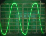
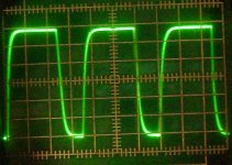
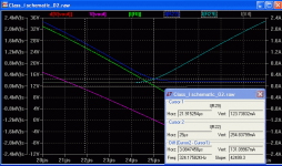
The plateau current is 124mA and the idle is 240mA. That setting pretty much eliminates the crossover distortion. Even at 20kHz (see below).
.
The circuit is effectively a follower. The distortion seems low enough for it to be used as a no-global-feedback amp.
The driving gain stage appears to drive into 400k ohms (50uA peak) unless I have miscalculated.
The output stage swing was clipping at 32 volts for 40V main supply so I reduced base stopper R21,R28 from 100 ohms to 10 ohms giving 36V swing which will help a bit.
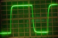
At 100kHz full swing the idle current increases to 1A as cross-conduction, so an input filter on the VAS stage is needed with roll-off -3dB from about 80kHz.
The need for two floating power rails is not a major issue. The negative 40V bias supplies can be relatively easily derived from the main supplies AC.
BTW I've added missing models for my PC and modified the run commands with Freq as a parameter. Also does AC plot.
It looks a pretty good idea to me. Well done.
Attachments
Hi apelizzo,
It does work well in the simulation that you posted. Thanks.
....It looks a pretty good idea to me. Well done.
Hello Ian,
Thanks for testing the circuit. I am glad that it looks promising and thanks for posting the updated circuit.
Do you think I should create a new thread? I don't really want to change topic in this thread.
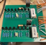
I just started experimenting the follower power stage on a test board and I'm trying to come up with a voltage stage without global feedback. Local feedback is ok.
Attachments
Last edited:
Hi apelizzo,
Your aim is no global feedback so doesn't fit the title.
PM UltimateX86 who started this thread. If he wants he can request admin to alter the title to be more compatible with your amp. Or admin can start a new thread with a title of your choice.
BTW MOSFET output version is attached with same idle currents😎. Amazing
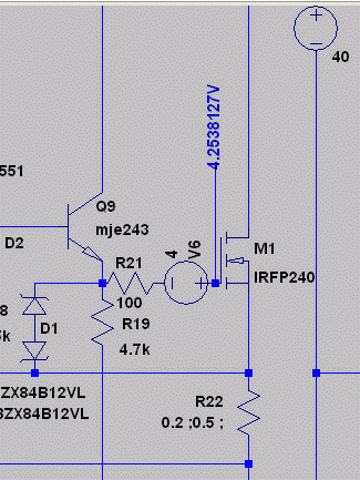
With an IRFP240 the output swing is lower by about 3V. One idea is to add 3V-4V to the gate as shown. Maybe 2 LED's in series for 3.5V with a 100nF shunt cap and 100uA pull-down resistor to -40V (470k?).
With an IRFP240 the gate stopper is increased to 100 ohms (needed for stability when recovering from clipping).
This thread is titled "Current Feedback MOSFET Circlotron"I just started experimenting the follower power stage on a test board and I'm trying to come up with a voltage stage without global feedback.
Your aim is no global feedback so doesn't fit the title.
PM UltimateX86 who started this thread. If he wants he can request admin to alter the title to be more compatible with your amp. Or admin can start a new thread with a title of your choice.
BTW MOSFET output version is attached with same idle currents😎. Amazing
With an IRFP240 the output swing is lower by about 3V. One idea is to add 3V-4V to the gate as shown. Maybe 2 LED's in series for 3.5V with a 100nF shunt cap and 100uA pull-down resistor to -40V (470k?).
With an IRFP240 the gate stopper is increased to 100 ohms (needed for stability when recovering from clipping).
Attachments

If he wants he can request admin to alter the title to be more compatible with your amp. Or admin can start a new thread with a title of your choice.
I think it's better if we start a new thread for zero global feedback circlotron. I prefer not to interfere with this one.
Yes I mentioned before about the ability of the circuit to self adjust so one can choose the output device according to his own preference and because it uses the same N polarity there would be a large number of options.BTW MOSFET output version is attached with same idle currents😎. Amazing
Yes, in the first circuit I left 100 ohms stopper resistor because I was playing with mosfets. I also left the two zener diodes to protect the gatesWith an IRFP240 the gate stopper is increased to 100 ohms (needed for stability when recovering from clipping).
I am going to open a new thread. Would you please copy all your comments to the new thread? I will post the name and link. Thanks again
Last edited:
There is a new thread for zero global feedback of Class i Circlotron.
https://www.diyaudio.com/forums/sol...bal-feedback-circlotron-200w.html#post6640345
Class i Zero Global Feedback Circlotron 200W
https://www.diyaudio.com/forums/sol...bal-feedback-circlotron-200w.html#post6640345
Class i Zero Global Feedback Circlotron 200W
With an IRFP240 the output swing is lower by about 3V. One idea is to add 3V-4V to the gate as shown. Maybe 2 LED's in series for 3.5V with a 100nF shunt cap and 100uA pull-down resistor to -40V (470k?).
That's a great idea as I was keen to use IGBT. The one I am trying now is the IGW30N60T just as an experiment. What I like about IGBT is their high S but probably not in our range. That's why I need to test them.
- Home
- Amplifiers
- Solid State
- Current feedback Mosfet Circlotron