Yes, unfortunately the arrows in the PMOS symbols do not point away from the gate, but that is how it appears in the model (OnSemi FQP3P20).
The remainder of the test circuit appears as shown in post #215. However, we are now talking about an amplifier with 50+ volt rails. In real life, an output stage with multiple MOSFET pairs and source resistors may be needed for best reliability.
I see. It's a p-channel MOSFET. I don't think you have studied the power MOSFET I want to use. It's vs-fa57sa50lc. One pair is enough. Its heat sink and pin are isolated. Therefore, it doesn't need to use heat shield. It can contact the heat sink directly, which is conducive to heat dissipation, can achieve greater power, and to a certain extent, alleviate the problem of heat runaway.
You may also want to look at the IXYS Linear L2 series MOSFETs, which are designed for linear service and include a DC SOA spec in their data sheets.
A new topic on the Circlotron without feedback.
https://www.diyaudio.com/forums/sol...irclotrons-negative-feedback.html#post6114927
https://www.diyaudio.com/forums/sol...irclotrons-negative-feedback.html#post6114927
Please provide the whole circuit diagram using dn2540 and fqp3p20. I find that unlike 215, I am not good enough to restore the correct circuit diagram. There is no output signal during the simulation test. If I just replace j113 with dn2540, the circuit can be simulated normally.In case it's needed, here's a diagram to clarify my earlier comment about zener clamps. I've also added a resistor to isolate each DN2540 gate from the low impedance of the zeners if they go into conduction, as this has been known to cause oscillation.
Also shown is a second method of cascoding a J113 input stage. Same basic principle as before, but instead of zener shunts to set the cascode DC level, this method uses two 39.2K resistors to form voltage dividers with the two 22.1K resistors, pulling up both BJT base voltages.
Micro-Cap 12 comes with models for both J113 and DN2540 devices, so I compared their performance as shown in these two circuit diagrams. I see similar frequency response but lower distortion with the DN2540, perhaps due to its much greater transconductance. Worth a try at least...
There is no output signal during the simulation test. If I just replace j113 with dn2540, the circuit can be simulated normally.
If the simulation works with the J113, I'd suspect a problem with the DN2540 circuit model. Here is what I used (copied from the Supertex library) in case it helps:
Code:
*DN2540 MODEL
*
.MODEL DN2540   NMOS (LEVEL=3   RS=1.05            NSUB=5.0E14
+DELTA=0.1      KAPPA=0.20      TPG=1              CGDO=3.1716E-10
+RD=11          VTO=-1.50       VMAX=1.0E7         ETA=0.0223089
+NFS=6.6E10     TOX=725E-10     LD=1.698E-9        UO=862.425
+XJ=6.4666E-7   THETA=1.0E-5    CGSO=2.50E-9       L=4.0E-6
+W=59E-3)
*
I'll work on a proper schematic for a 100W+ amplifier and post here if UltimateX86 is OK with that.
If the simulation works with the J113, I'd suspect a problem with the DN2540 circuit model. Here is what I used (copied from the Supertex library) in case it helps:
Code:*DN2540 MODEL * .MODEL DN2540 NMOS (LEVEL=3 RS=1.05 NSUB=5.0E14 +DELTA=0.1 KAPPA=0.20 TPG=1 CGDO=3.1716E-10 +RD=11 VTO=-1.50 VMAX=1.0E7 ETA=0.0223089 +NFS=6.6E10 TOX=725E-10 LD=1.698E-9 UO=862.425 +XJ=6.4666E-7 THETA=1.0E-5 CGSO=2.50E-9 L=4.0E-6 +W=59E-3) *
I'll work on a proper schematic for a 100W+ amplifier and post here if UltimateX86 is OK with that.
This is the model of dn2540, which is right, officially released. It is a depletion type MOSFET. In fact, I have made a preamplifier with it. The source resistance is 10 ohms, and the working current is close to 100 mA. The sound is very good.
A new topic on the Circlotron without feedback.
https://www.diyaudio.com/forums/sol...irclotrons-negative-feedback.html#post6114927
HI jpatay,
This is the amp so I spoke to you in December, but I just invert the schematic and put the Power Jfet that you proposed on your thread
with the difficulty of finding input jfets, I thought why not bipolar, so I tried to simulate this one
Attachments
HI jpatay,
This is the amp so I spoke to you in December, but I just invert the schematic and put the Power Jfet that you proposed on your thread
with the difficulty of finding input jfets, I thought why not bipolar, so I tried to simulate this one
Yes, I remember our conversation. Good job!!!
 It would be nice to check this circuit in work.
In the circuit model, filtering each supply rail individually as shown in the attached diagram works well as an alternative to using C7 for reduced front end supply noise.
With this method, noise currents return directly to the supplies without crossing signal ground. Front end supply voltage is reduced slightly (3V in this example), but apparently not enough to affect performance.
HI Joe,
it remains to define the right values for RC
in simulation it would seem that with a low capalike 50uF it is better in place of 330
the rejection is realy better with a 1uf
Attachments
it remains to define the right values for RC
I see a different result in my model, but we may be measuring differently. In my case I add two in-phase sine voltage sources, one in series with each supply voltage source. My assumption is that the noise of greatest concern is mostly the same on each supply. For this type of noise, higher C values give lower noise across the output.
Just a simulation test but good performance without global feedback
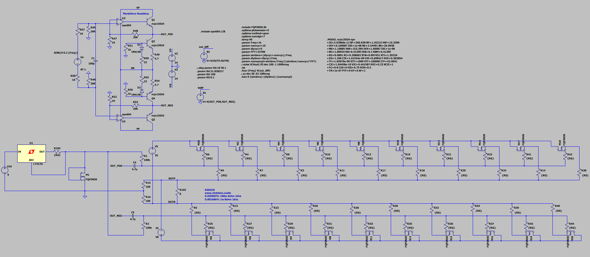
10X fqp3n30 have lower input capacitance than only one IRFP150N
10X fqp3n30 have lower input capacitance than only one IRFP150N
Last edited:
From my own experience I will say that I can’t listen to amplifiers with feedback for a long time, but without feedback I can listen all day.
I agree with Jpatay regarding the sound of an amplifier with feedback.
I explain where I found the difference according to my perception.
I own and listen to Class A 45W single ended without feedback, Class A -AB 50W push-pull without feedback then a series of traditional push-pull BJT and Mosfet including Quad405 design with feedback. I pull for example one difference that matters to me between the "with feedback" and "without feedback" groups. Even if the tone of both groups are pleasant I find that non feedback amplifiers have the sound stage very stable. The violin is always in the same position, the singer the same and all is in order. The amplifier with feedback presents to my ears a sound stage where at particular notes instruments change position. (Also when it changes position it casts shadow over something else). And that is why even if the amplifier with feedback has distortion figure is 0.000xx % at 1KHz, I suspect that there is phase shift error generated by the global feedback during music listening. For that reason I reject such amplifiers which I call "Leslies". It's a shame because I like the sound of some amplifiers with feedback but unfortunately I found the stability of the sound stage an issue so I can't listen to them for long time.
Last edited:
10X fqp3n30 have lower input capacitance than only one IRFP150N
Seb, I also wanted to put several MOSFETs at the output, but it seems to me that the result will be the same. In Mosfet with a large capacity and high power, several smaller transistors are already installed on one crystal and are connected in parallel. But I could be wrong. 😉
I like the idea of increasing S and the approach to zero global feedback in the output stage.
I would like to try with a pair of IXXN110N65C4H1 IGBTs. Spice models are available from IXYS. The IGBT have much lower input capacitance than an equivalent full mosfet.
If it's possible at reasonable cost of power dispersion due to high Vge, I would like to research on a class B current dumping circlotron. Class B circlotron stage would not need temperature tracking
Attachments
Last edited:
Seb, I also wanted to put several MOSFETs at the output, but it seems to me that the result will be the same. In Mosfet with a large capacity and high power, several smaller transistors are already installed on one crystal and are connected in parallel. But I could be wrong. 😉
10X fqp3n30 have lower input capacitance than only one IRFP150N but better transconductance, so the result is not the same.
simulation shows in the performance of the amp, lower distortion, lower current on driver at high frequency
I agree, but this circuit needs to be assembled on a breadboard. If Rout decreases significantly, then it makes sense to repeat it.
I like the idea of increasing S and the approach to zero global feedback in the output stage.
I would like to try with a pair of IXXN110N65C4H1 IGBTs.
Yurik tested IGBT transistors. He wrote about them here:
JFET-only Circlotrons without negative feedback.
- Home
- Amplifiers
- Solid State
- Current feedback Mosfet Circlotron