The sound is super!
Yura, try an amplifier with an unbalanced input, as suggested by Joe.🙂
Last edited:
Hi Yura, welcome to the family, what is your mosfet ?
Why using an unbalanced source if you have a balanced one ?
Yura, try an amplifier with an unbalanced input, as suggested by Joe.🙂
Why using an unbalanced source if you have a balanced one ?
Last edited:
Hi Yura, welcome to the family
Why using an unbalanced source if you have a balanced one ?
For the experiment, it will be interesting. And most people do not have a balanced source.
Hi, Seb!
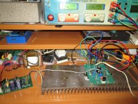
Transistors: J113-2SA1380-IRF4905-chinese transistor labeled as 1058.
IRFP150 ordered, coming to me.
Transistors: J113-2SA1380-IRF4905-chinese transistor labeled as 1058.
IRFP150 ordered, coming to me.
For the experiment, it will be interesting. And most people do not have a balanced source.
Yes, my thoughts exactly. This project will have broader appeal if it can work reasonably well with an unbalanced input.
Yes, my thoughts exactly. This project will have broader appeal if it can work reasonably well with an unbalanced input.
Hi Joe, Yura included an amplifier with an unbalanced input. The amplifier works, but he will write in more detail himself.🙂
Yes, my thoughts exactly. This project will have broader appeal if it can work reasonably well with an unbalanced input.
IMO for reasonably well unbalanced input amp operation second differential VAS pair stage( 2x KSA1381) need one common CCS inserted in emiters tail .
I will not say anything yet. 🙂 Because I did not have IRF9520 and IRF4905 was temporarily installed. Accordingly, it was necessary to reduce the resistance of R15 (470R) to 82R. As a result, I got a lot of odd harmonics.
IMO for reasonably well unbalanced input amp operation second differential VAS pair stage( 2x KSA1381) need one common CCS inserted in emiters tail .
We accomplish the same thing here using M3 to amplify any common-mode voltage across the Vas tail resistor and feed it back to the Vas inputs out of phase. This corrects any imbalance in the Vas itself or in the drive coming from J1-J2.
Last edited:
I did not have IRF9520 and IRF4905 was temporarily installed.
An IRF4905 should work also. Could the part be mislabeled or defective?
An IRF4905 should work also. Could the part be mislabeled or defective?
I suspect that the counterfeit J113.
Seb, thanks for the offer! No need to send, postage will be more than the cost of transistors. 🙂 I will find transistors here.
Re: Removing C7 from Circuit
Hi Sébastien,
You are absolutely correct, thank you.
I've now followed up on this using my Micro-Cap circuit model with various combinations of common mode and differential noise signals in series with the supply rails, and using both balanced and unbalanced input sources. In every case I tried, adding C7 of any value increased the power supply noise seen on the output rails.
I did not foresee this result because the "RCR" method of creating a fixed positive supply for the front end was used successfully in the original EV Circlotron vacuum tube amplifier and in other similar designs that followed.
I can now appreciate a key difference here, which is that the noise current passing through C7 is many times higher than in earlier tube designs. This causes it to add significant noise to the output rails as it passes through R19-R20 back to the supplies. Negative feedback can help reduce this, but the result is still worse than if we simply let the front end reject the noise on its own.
As for my concern about possible common mode oscillation, my model does show a broad peak in the 10-20 MHz range in the common mode noise seen at the M3 source terminal without C7 installed. Adding 150 pF at the C7 position damps this peak, but so also does adding 150 pF from collector-to-base on each Vas transistor, which in my model also nicely stabilizes the circuit. So in the end, C7 is not needed for any reason.
In short, I agree with your suggestion to remove C7 from the circuit entirely, as long as your preferred HF compensation scheme also damps any noise peaking you may otherwise see at the M3 source terminal. Thanks again for raising this issue!
What do you think about removing the 100uf cap? On listening I think it's better, and in simulation it greatly improves PSSR
Hi Sébastien,
You are absolutely correct, thank you.
I've now followed up on this using my Micro-Cap circuit model with various combinations of common mode and differential noise signals in series with the supply rails, and using both balanced and unbalanced input sources. In every case I tried, adding C7 of any value increased the power supply noise seen on the output rails.
I did not foresee this result because the "RCR" method of creating a fixed positive supply for the front end was used successfully in the original EV Circlotron vacuum tube amplifier and in other similar designs that followed.
I can now appreciate a key difference here, which is that the noise current passing through C7 is many times higher than in earlier tube designs. This causes it to add significant noise to the output rails as it passes through R19-R20 back to the supplies. Negative feedback can help reduce this, but the result is still worse than if we simply let the front end reject the noise on its own.
As for my concern about possible common mode oscillation, my model does show a broad peak in the 10-20 MHz range in the common mode noise seen at the M3 source terminal without C7 installed. Adding 150 pF at the C7 position damps this peak, but so also does adding 150 pF from collector-to-base on each Vas transistor, which in my model also nicely stabilizes the circuit. So in the end, C7 is not needed for any reason.
In short, I agree with your suggestion to remove C7 from the circuit entirely, as long as your preferred HF compensation scheme also damps any noise peaking you may otherwise see at the M3 source terminal. Thanks again for raising this issue!
Re: Dual Rail Filtering
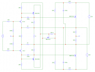
In the circuit model, filtering each supply rail individually as shown in the attached diagram works well as an alternative to using C7 for reduced front end supply noise.
With this method, noise currents return directly to the supplies without crossing signal ground. Front end supply voltage is reduced slightly (3V in this example), but apparently not enough to affect performance.
Attachments
Hello Joe, thank you for the idea it looks promising, at the moment I am no longer involved in this project, in the process of separation from my son's mom
as soon as the situation is stabilized I will have more time and space for the project, less need to tidy up my workshop 🙂
as soon as the situation is stabilized I will have more time and space for the project, less need to tidy up my workshop 🙂
Hi,
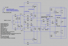
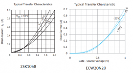
What have to modify when I like rather to use lateral MOSFET instead of IRFP trans. I thought 2SK1058/ECW10N20-S/ECW20N20-S types but their Vgs parameters lower.
If I good understand the value of Mosfet Vgs come from the R12-392ohm and I12 is 10,03mA. So Vgs=392*0,0103=3,9V. In the simulation the Id bias of IRFP150n is 300mA, If I want same bias Id of lateral MOSFET's, the Vgs=0,8V Id=200mA of 2SK1058 and the I12 same 10,03mA so new R12=80ohm (0,8/0,01). I this case bias of ECW20N20 would be Id=400mA. Is it correct?
Gate resistors (100-300 ohm) before M1/M2 not necessary?
Gy.
Attachments
Gate resistors (100-300 ohm) before M1/M2 not necessary?
I put 91 ohms in the gates, I did not see any difference. Maybe for 2SK1058 and it will be necessary 100 Ohms.
Hi,
What have to modify when I like rather to use lateral MOSFET instead of IRFP trans.
The easiest option is to replace the 390 Ohm resistor with two and calculate the value of the lower resistor so that the voltage on it is 0,8 V.
- Home
- Amplifiers
- Solid State
- Current feedback Mosfet Circlotron