Yes with 24v and 1k , J113 selected with lower current 1.2/1.3ma
Measured by such a circuit?
Attachments
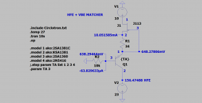
for the vas i have made that
I do not know if it's optimal but it allows to have the VBE and the HFE at the same time at about 10mA and 240mW
YouTube : I took the first value : IC =10,92ma VBE= 540mV V(10k)=632mV IB=63,2uA HFE=172
I do not know if it's optimal but it allows to have the VBE and the HFE at the same time at about 10mA and 240mW
YouTube : I took the first value : IC =10,92ma VBE= 540mV V(10k)=632mV IB=63,2uA HFE=172
Attachments
Last edited:
Hi Sebastion!
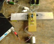
I launched your circlotron on the
homemade pcb.
So far, so good.
Found at home BD140, IRF1010E.
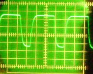
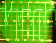
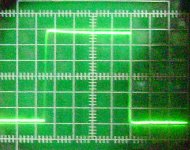
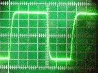
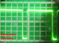
Matched pairs j113. The input transformer is taken from a BEAG-080 tube amplifier. The 10 kHz and 20 kHz meanders are bad, but the reason is the BEAG transformer.
Sebastion and gionag, thanks for a great project.
I launched your circlotron on the
homemade pcb.
So far, so good.
Found at home BD140, IRF1010E.
Matched pairs j113. The input transformer is taken from a BEAG-080 tube amplifier. The 10 kHz and 20 kHz meanders are bad, but the reason is the BEAG transformer.
Sebastion and gionag, thanks for a great project.
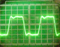
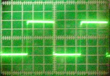
The input transformer is taken from a BEAG-080 tube amplifier. The 10 kHz and 20 kHz meanders are bad, but the reason is the BEAG transformer.
Hi jpatay,
Would you mind testing without the input transformer, just driving the amplifier unbalanced? It would be interesting to see if that's a practical option.
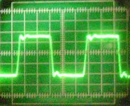
I put the meander on one shoulder.
I think this means you applied the square wave directly to one amplifier input terminal, is that correct? If so, you should connect the other amplifier input terminal directly to signal ground.
I think this means you applied the square wave directly to one amplifier input terminal, is that correct? If so, you should connect the other amplifier input terminal directly to signal ground.
Yes. I did not connect the second entrance to the ground. It’s already dark, I’ll look again tomorrow.🙂
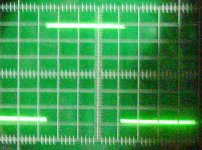
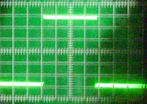
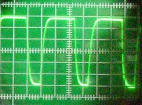
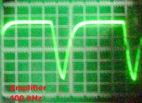
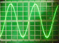
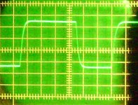
Thank you jpatay. Did the 6 kHz square wave look symmetrical? If so, I think it will be OK for audio. If not, it may be possible to fix by adjusting the compensation. I'll look into that when I can.
Last edited:
Did the 6 kHz square wave look symmetrical?
Yes. Frequency response: 0 - 70 kHz ( 0 dB).🙂
Thank you jane, I must invert in measurement equipment to check mine
with BD140 you should decompensate
with BD140 you should decompensate
Last edited:
with BD140 you should decompensate
It may also help to replace C1 and C2 with a single capacitor connected directly across the input JFET gates, bypassing ground.
indeed, thank you
you know how to increase the idss of a jfet model ?
.MODEL J113 NJF(VTO=-1.2854 BETA=9.25964m BETATCE=-0.5 LAMBDA=3.03839E-2 RD=1.30170 RS=1.30170 CGS=1.05000E-11 CGD=1.20000E-11 PB=5.04493E-1 IS=9.86870E-16 XTI=3 AF=1 FC=0.5 N=1 NR=2 MFG=PHILIPS)
you know how to increase the idss of a jfet model ?
.MODEL J113 NJF(VTO=-1.2854 BETA=9.25964m BETATCE=-0.5 LAMBDA=3.03839E-2 RD=1.30170 RS=1.30170 CGS=1.05000E-11 CGD=1.20000E-11 PB=5.04493E-1 IS=9.86870E-16 XTI=3 AF=1 FC=0.5 N=1 NR=2 MFG=PHILIPS)
Last edited:
- Home
- Amplifiers
- Solid State
- Current feedback Mosfet Circlotron