I don't recall referring to Stasis amps as Current Dumping, but thanks for posting the schematic...
Now that I see your post Nelson I recall hearing the Threshold Stasis 1 before knowing or hearing anything about you or Threshold before. It was one of those sonic experiences that I have never forgotten. Unfortunately at the time my wife refused to work the streets to purchase it...
Having seen your circuits many times since I suspect many still don't realize the sonic significance of those cascode networks included... and that you are well aware what impact they had in its creation.
The main difference is that output voltage errors below left feed directly to the emitters of the current mirror. This forms a high current "CFA" form of output buffer loop. An alternative shown on the right doesn't have the additional class B network. This network was built as part of a multiple feedback loop network that is not shown here, including feedback from the op-amp output back to its input.Yay. An interesting take on that idea was published by @fakel on the (Russian-speaking) forum.vegalab.ru:
View attachment 1396337


Although there are a myriad of variants network that can be configured around the floating current mirrors made up of Q3 through Q6, these provide thermal tracking in preventing thermal runaway, that at the same time eliminates the need for emitter degeneration resistors. High current fluctuations on the output side feeding the load limits the turn off of the opposing transistors, in that the increase in turning on of either device is logarithmic in absence of series degeneration resistances. This speeds up response and minimizes the degradation caused by complete turn off of either device and the miller feedback capacitances by the minimization of voltage variation between the emitter pairs and consequently collectors.
In a network that uses non-darlington bipolars as Q1 and Q2 the current mirrors must be capable of full load current and also have sufficient quiescent current to provide the base current variance for full output current. For fun this network was built on a breadboard using a +/- 15 volt supply using some 2SB649's and 2SD669's for the mirrors, being bolted together with A1943/C5200 transistors for Q1/Q2.

Nice 👍
for me it's like playing with Lego Bricks.
Infinite combinations with bjt's - just as toys.
for me it's like playing with Lego Bricks.
Infinite combinations with bjt's - just as toys.
Even though Nelson Pass Stasi 1 Amp is a mighty heavyweight (all in a positive sense), let's stick to the topic here.
a) the overriding concern of jxdking
and
b) the sub-context of the name and principle giver, the Quad 405.
If you make a small signal replacement circuit for the two cases (dumper off and dumper on) of passing through the signal zero crossing, the secret is out in the open.
This method is valid for quite a long time in good approximation. The first thing to realize is that an explanatory model depends solely on the dualistic transformations adopted. Do we form current source models and calculate with currents and conductance values or do we form voltage source models with internal resistances and consider voltages. Often mixed models are also necessary and it becomes a back and forth transformation. However, the present case is not quite so complicated. But first of all, you should not approach the resolution with a biased perspective, for example the idea that a bridge structure must be present.
I don't think it makes sense (at the moment) to publish the necessary networks here, because they are the visual proof for the thesis.
The thesis is:
there is no usable bridge structure (it is rather the mathematical integration and differentiation [of the time function of the input and output signal] - if you like), but a so-called Miller loop in which the complete output stage (the dumper) is virtually embedded. Conversely, this means that no secret or previously unknown magic circuit is responsible for the low THD of the entire amplifier, but rather the DC or the open loop gain of the system (when the dumper is switched off). This runs horizontally across the audio frequency range up to the first cut-off frequency. The core (the IP and VA stage) is implemented in two stages, with a special dynamic feature in the collector circuit of the last stage. If you close the local loop over the second stage with the capacitive reactance of the C=127.7pF capacitor (keywords are dominant pole and Miller compensation, capacitance), i.e. connect node A with C' in terms of ac, then a familiar picture emerges, or the course of the usual OLG representation with a relatively low 1st cut-off frequency.
...
tpc
The thesis is:
...
The frequency-dependent inner loop (a voltage-current feedback) is now completely enclosed globally at node C, the emitter of the first stage, with the R2=500Ohm current-voltage feedback, and the final bandwidth of this amplifier is thus determined independently of the resulting CLG.
RN=180Ohm at the current summation node C now determines the final voltage gain without further consideration of the internal signal-source resistance at the base electrode of the input transistor TR2 (negative feedback also takes place at this point or node, which is usually neglected). The dynamic description of the second (composit) stage is elementary, but the only important thing for the thesis is the bootstrap effect present here, which is responsible for the fact that node B follows node A ---> therefore these two points are virtually identical and the OPS (the complete composit) is thus a member of the Miller loop. At the same time, the inductance L=3µH is now dynamically parallel to R1=47Ohm. Theoretically, this consideration now also determines the impedance of node D of maximum 0.38Ohm at 20kHz.
Since we consider the present amplifier as a whole and set up a complete equivalent network, it must be noted that the node impedances (we look into the node of the small signal model from all sides) C and C' are not identical, nor should R1 simply be regarded as a so-called feedforward resistor, because it is elementary for the function of inner bootstrap at the second stage - a little bit SRPP like, at the same time is also the complete composit, with included dumper-outputstage, a follower, a bootstrap.
...
tbc
...
The frequency-dependent inner loop (a voltage-current feedback) is now completely enclosed globally at node C, the emitter of the first stage, with the R2=500Ohm current-voltage feedback, and the final bandwidth of this amplifier is thus determined independently of the resulting CLG.
RN=180Ohm at the current summation node C now determines the final voltage gain without further consideration of the internal signal-source resistance at the base electrode of the input transistor TR2 (negative feedback also takes place at this point or node, which is usually neglected). The dynamic description of the second (composit) stage is elementary, but the only important thing for the thesis is the bootstrap effect present here, which is responsible for the fact that node B follows node A ---> therefore these two points are virtually identical and the OPS (the complete composit) is thus a member of the Miller loop. At the same time, the inductance L=3µH is now dynamically parallel to R1=47Ohm. Theoretically, this consideration now also determines the impedance of node D of maximum 0.38Ohm at 20kHz.
Since we consider the present amplifier as a whole and set up a complete equivalent network, it must be noted that the node impedances (we look into the node of the small signal model from all sides) C and C' are not identical, nor should R1 simply be regarded as a so-called feedforward resistor, because it is elementary for the function of inner bootstrap at the second stage - a little bit SRPP like, at the same time is also the complete composit, with included dumper-outputstage, a follower, a bootstrap.
...
tbc
The Thesis:
If you follow this thesis, which ultimately only states that the general agreement of the superficial functional descriptions may be correct on their own, but unfortunately does not apply to the Quad 405 or is not applicable, then this has immediate consequences for the known attempts to prove the functionality of the formulated current dumper principle.
If you start with a bridge (which does not exist in the equivalent network) and remove the R1, for example, in order to have the CD principle directly proven by comparing the u(t) of the bridge, or even the THD, with and without a feedforward resistor, you have unfortunately fundamentally changed the inner bootstrap of the second stage and not a desired feedforward.
This half-baked method of CD proof is completely unsuitable. It would be perfectly acceptable as a simple and very quick test if the second stage of the current-voltage feedback overall system were not a composite, but if there were actually two independent output stages, i.e. two amplifiers - but that is absolutely not the case.
HBt.
Typos, sorry:Even though Nelson Pass Stasi 1 Amp is a mighty heavyweight (all in a positive sense), let's stick to the topic here. (...) tpc
STASIS
&
tbc
Aside from that, no one seems to want to post a rebuttal or even a supporting substantiation.
😢
However, what is shown, is some fantastic hand drawn circuit diagrams - like art. Frame them. If not for the circuit that I can't comment due to lack of insight but for the sheer beauty of ink.is not shown here,
//
Quad 405


Gain -----> 75.5dB
r_out -----> 53Ohm
One should really (and this can only be emphasized urgently) consider TR8 & TR10 as a whole, as a replacement Darlington, because that's all it is. Output node D is relatively low impedance! And all this (still) without any global current-controlled voltage feedback.
HBt.audio
Node B

Gain -----> 75.5dB
r_out -----> 52.5 Ohm
The replacement Darlington (TR8&TR10) is always in play - and the entire construction is called SRPP in RF, RF tube technology. To consider the 47Ohm resistor as FFWR in a magic bridge structure is absolutely not helpful, even if one could diplomatically say that everything could depend on the place of observation, the substitute perspective. One could take it really far, from eyewash to self-deception.
Now the Quad 405 replacement model is two-stage and globally current-controlled voltage-feedback coupled.
R2=500Ohm

Gain is now 11.54dB
r_out at
all data without C=127p7 and TR9 (the dumper).
R2=500Ohm
Gain is now 11.54dB
r_out at
- Node D is 10m5 Ohm
- Node B is also 10m5 Ohm
- Node A is 131m5 Ohm
all data without C=127p7 and TR9 (the dumper).
A sacred cow slaughtered
QUAD 405
with C=127p7 F - and dumb Dumper TR9 always off!

The internal resistances of the nodes under consideration are of course unchanged ... I will be happy to add 'C' later.
A mysterious bridge does not exist, nor does an FFWR. The 47Ohm resistor is an integral part of the second stage, the entire composite.
HBt.audio
QUAD 405
with C=127p7 F - and dumb Dumper TR9 always off!
The internal resistances of the nodes under consideration are of course unchanged ... I will be happy to add 'C' later.
A mysterious bridge does not exist, nor does an FFWR. The 47Ohm resistor is an integral part of the second stage, the entire composite.
HBt.audio
As the TR9 dumper does not switch on abruptly, but intervenes gently in the action, it can be completely ignored in the slightly simplified representation of the situation.

Despite all the euphoria and anticipation, up to 120dB DC gain in the core of the global feedback system is the most important part of all. The effect of the unusual integrated error cancellation, which contributes a maximum of 7%, is hardly worth mentioning, but it is the all-important unique selling point of QUAD compared to its competitors at the time. The only problem the 405 has is the switch-off torque of the TR9 dumper.
HBt.audio
- The 100% current imprint of the "ring" leads to the conclusion that C' is the same as C, but they are not the same, but their node impedance is dynamically the same
- The phase rotation between these points must be |180°|, otherwise it would not be possible to globally counter-couple the ring at node C at this point
- For the non-existent AC bridge, this point (the different phase shifts, angles of the vectors) could be the decisive sticking point of the CD principle!
Despite all the euphoria and anticipation, up to 120dB DC gain in the core of the global feedback system is the most important part of all. The effect of the unusual integrated error cancellation, which contributes a maximum of 7%, is hardly worth mentioning, but it is the all-important unique selling point of QUAD compared to its competitors at the time. The only problem the 405 has is the switch-off torque of the TR9 dumper.
HBt.audio
Attachments

Thank you for your attention and please do not hesitate to contact me if you have any questions.
😉
☕

😉
☕
I also think that those that fully understand the working of nfb would immediately recognise the change in feedback factor if the dumpers start to conduct.
Jan
Dear Jan,
there is only one dumb Dumper, namely TR9.
😎
Or do you have a different opinion or view?
greetings,
HBt.
Psst I love gnfb!
Looks as good as I can understand it hbtaudio. As an aside they do make op-amps with high voltage capability.Aside from that, no one seems to want to post a rebuttal or even a supporting substantiation.
😢

Disclaimer
Current dumping audio amplifier Output power transistors' non-linearity does not appear in amplifier transfer characteristic
by P. J . Walker
Acoustical Manufacturing Co. Ltd.
wireless world 12/1975
In no way do my statements all above call the original article into question, quite the opposite in fact. The only thing is that Mr. Walker keeps the real secret of the circuit and the trick to himself, correctly pointing out the currents (in the ring) again and again. He does not even mention a real existing bridge; his description leads, whether consciously or unconsciously, on the wrong track - thus the product is protected beyond the actual patent. At the same time, all the subsequent rumors and disputes, the usual wrangling over competence, are a welcome advertisement for QUAD.
HBt.
Psst
The text explains how the actual error is finally reduced. You just have to read and understand it. Mr. Walker said it openly, but that has nothing to do with ..!
In any case, I take my hat off to Mr. P. Walker - chapeau.
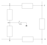
The Ring - "eine Masche"
Now that we have finally mentioned and identified the ring, the secret of the ring master can be revealed.
To do this, we need to know what the nodes are and what is between them in the boxes. Later, we walk along the ring, once clockwise and once counterclockwise, and set up a simple mesh equation for each.
The simulation showed that the node impedances of nodes C and C' are low impedance (I hadn't revealed this yet), it also showed that u(t)C'C / u_inp(t) = 1 and that there is a phase difference between the nodes in terms of voltage. In plain language, this means that we can replace the corresponding box with an AC voltage source. This voltage source (ideally with an internal resistance of zero ohms between the terminals) is, or corresponds to our signal source, what we want to amplify!
...
tbc
Attachments
We should keep in mind that B follows A virtually (through the inner bootstrap, which always remains unmentioned!), so we can dynamically claim that R1 & L are parallel to each other. P. Walker even writes this in the above-mentioned article, but the simplified principle circuit with operational amplifier and separate push-pull B output stage distracts from the actual facts. But Mr. Walker mentions this correct fact. While a completely different one is somewhat obscured, namely the descriptive perspective. If you look at the picture of the ring based on network theory, you can also see that C & R2 must inevitably lie parallel to each other dynamically.
I don't know if I can reveal the complete picture before Christmas? Santa Claus is coming today in northern Germany - and I have to stick to the conventions, even though I'm a complete non-believer - I could just work today.
HBt.

I don't know if I can reveal the complete picture before Christmas? Santa Claus is coming today in northern Germany - and I have to stick to the conventions, even though I'm a complete non-believer - I could just work today.
HBt.
- Home
- Amplifiers
- Solid State
- Current Dumping with OPAMP