

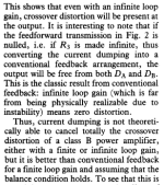
No. FB can only bring the error to zero in the limiting case of infinite open loop gain. FF can in theory bring the error to zero if the correction factor is exactly one, which is possible in theory but not in practise of course.Theoretically, fb & ffw systems can correct the remaining error to zero, which is why we like to speak of error correction. In practice, of course, this is impossible.
I also think that those that fully understand the working of nfb would immediately recognise the change in feedback factor if the dumpers start to conduct.
Jan
Last edited:
The idea that the case of the open loop could exist in practice should not be taken lightly
With a gain of +120dB, there will always be a controlling DC feedback, otherwise the output of our last stage will hit one of the two supply rails and stay there.
So it is compared to zero, right from the start. There is no such thing as a non-controlled zero in any real and practical amplifier.
Neither does a dead zone, because we control the zero. Is there a discontinuity while passing through this controlled zero? Yes, this exists in reality - but it is extremely short, with our enormous Vuo (often also referred to as dc-gain) the time difference also practically tends towards zero.
HBt.
Yes! A yes is correct.
I have said absolutely nothing to the contrary. I also know the theory inside out, you are not alone here.FB can only bring the error to zero in the limiting case of infinite open loop gain.
That's exactly what I wrote above.FF can in theory bring the error to zero if the correction factor is exactly one, which is possible in theory but not in practise of course.
To whom are you addressing right now? Of course, a change will come about when TR9 is fully operational.I also think that those that fully understand the working of nfb would immediately recognise the change in feedback factor if the dumpers start to conduct.
Jan
BTW A change of feedback factor is what you get when in a 'normal' amplifier where the feedback factor is determined by the ususal 2-resistor divider, you change one of the resistor values.
Just to have the term clear 😎
Jan
Just to have the term clear 😎
Jan
I have had this suspicion for some time now.I have some weird theory but at the same time i dont think that such a detail could have escaped WWorld authors
who were a proven mathematicain and an equally proved enginer, not counting all other authors who added
their own analysis to the subject.
He may have been buried under other priorities, but he is now more alive than ever.
It's all too human. Hopefully there is nothing more behind it than just a pure admission. That one denies to oneself.
Here are two more papers on the subject:This was already posted here :
https://www.google.com/url?sa=t&sou...4QFnoECBUQAQ&usg=AOvVaw2TE1JT7j-rMcpW-_II9Atg
The second one is only partial:
Attachments
Yes, Jan, I know all that - this term is clear.BTW A change of feedback factor is what you get when in a 'normal' amplifier where the feedback factor is determined by the ususal 2-resistor divider, you change one of the resistor values.
Just to have the term clear 😎
Jan
Nevertheless, it is good that you have worked out this simple connection. If I pull one of my old Leitz folders from the shelf and open it, I'll find a lot of rectangular framed boxes there. In these boxes I will probably make out a small "k" through the totally yellowed sheet of paper.
😎
This is one of the many letters to the editor that I mentioned previously.The second one is only partial:
A manufacturer would welcome a circuit which does not need an employee tweaking a bias pot during production.
A manufacturer would prioritise this, over any theoretical promise of zero distortion, providing that performance was not compromised, of course.
They exist, they have low distortion, there is no pot to tweak.
Last edited:
TR9 should have been identified as TR#2.... after all it is a dumper...Of course, a change will come about when TR9 is fully operational.
Thanks for the paper, this is explanatory but this doesnt change things, notice that they get higher THD when increasingHere are two more papers on the subject:
https://www.google.com/url?sa=t&source=web&rct=j&opi=89978449&url=https://schematicsforfree.com/files/Audio/Circuits/Power%20Amplifiers/Theory/Current%20dumping%20-%20does%20it%20really%20work%20-%20Theory%20and%20Practice.pdf&ved=2ahUKEwj4z7v-sLaKAxV_TaQEHZyFBu4QFnoECBUQAQ&usg=AOvVaw2TE1JT7j-rMcpW-_II9Atg
The second one is only partial:
the NFB over a given point, wich is not logical at all, how can this be explained.?.
That's right, that's the dumper!TR9 should have been identified as TR#2.... after all it is a dumper...
@wahab
I can't help but get the impression that there is no interest in the actual mechanism of action. It obviously doesn't interest anyone...
Let's give up. The second PDF, the one-page letter, contains a much bigger hammer. I stumbled across it immediately.
I feel sad
😢 now.
Bye,
HBt.
Attachments
Since I have just lost all enthusiasm and Santa Claus is at the door, I will dispense with the final explanation, the transformations and conversions... the proof of the thesis has long been provided, all that is missing is the formulation of the thesis itself.
Oh, what the heck:
Dear reader,
simply consider the (virtual) node A' as roughly equal to node A, now node B is tied to node A because it corresponds to A'. The serious significance of this dynamic fact has blatant consequences and completely collapses the formulated CD thesis.
I'm so sorry, but if you pour the current point of consideration into an equivalent circuit diagram of control engineers or communications engineers, even the mathematical proof can be easily provided.
But now I have a headache. Where has Haudegen gone when you need this guy..?
Tschüß,
HBt.
Attachments

It is true that I don't care much personally to understand the 405 completely, oftentimes most things just enough to do my own thing. Perhaps you can provide some thoughts on the following HBt.
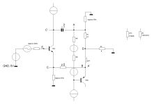
What is being referred to as current dumping with an op-amp can be loosely considered in a network built for personal use some time ago. The basic configuration is shown below. The transistors Q3/Q4/Q5/Q6 (with the other transistors on top and bottom) forms floating current mirror clusters. The output side forms a basic unity gain CFA type device whereupon the inductor and the R across it forms a low impedance path for DC as supporting stability. Because Q3/4/5/6 all operate at low voltage this makes thermal tracking fairly easy to control. Note that Q1 and Q2 doesn't show any biasing and could be replaced with darlingtons, Mosfets or some other devices.

What is being referred to as current dumping with an op-amp can be loosely considered in a network built for personal use some time ago. The basic configuration is shown below. The transistors Q3/Q4/Q5/Q6 (with the other transistors on top and bottom) forms floating current mirror clusters. The output side forms a basic unity gain CFA type device whereupon the inductor and the R across it forms a low impedance path for DC as supporting stability. Because Q3/4/5/6 all operate at low voltage this makes thermal tracking fairly easy to control. Note that Q1 and Q2 doesn't show any biasing and could be replaced with darlingtons, Mosfets or some other devices.
I would have a headache too, if I was trying to analyse a circuit by using a different circuit, which was nothing like the circuit I was trying to analyse.But now I have a headache.
This statement is absolute nonsense.I would have a headache too, if I was trying to analyse a circuit by using a different circuit, which was nothing like the circuit I was trying to analyse.
Furthermore, there is no need to defend the English quad xxx.
also complete nonsense, and of course a quiescent current (will) flows through your Q1 and Q2.Note that Q1 and Q2 doesn't show any biasing and (...)
- Home
- Amplifiers
- Solid State
- Current Dumping with OPAMP