Center taped is usually made by internally connecting two separate windings. You can break that connection and you'll have two separate secondaries.
Or. make the cap. mult. with P-ch MOSFET for the negative rail so the GND goes uninterrupted from center tap.
Thank you juma
I did checked the transformer (it is inside in old project) and yes I can separate the center tap wire.
There is two wire inside that tubing.
So happy
 , now I can go on and collect some of the missing parts.
I do have all the mosfets including the J-fets.
Those are the hard to find parts.
Greetings Gabor
Measure them and calculate. Think like this:
understood the schema, my difficulty is to calculate, or find the value per measurement of R1 and R2
in the "standard" F5 EUVL uses one J74 with idss 0,8mA more than the K170 and adds R1 of 5ohm to degenerate the J74 to have the same gm as the K170
This is because the J74 (even with matched Idss) is not a true complementary of the K170. the trick of EUVL is to add degeneration to the J47 to match the characteristic of the 170
In my case with 2x K74GR, should I still use 0.8mA more total Idss than the K170 and 5ohm for R1 and R2?
paralleling fets does increase the gm of the resulting fet?
How do you expect someone to give you a solution on a silver platter if you don't supply the basic data about the JFETs that you got ?
Use the search button, read Borbely's JFET articles, measure your JFETs - asking already answered questions over and over again won't take you very far...
Use the search button, read Borbely's JFET articles, measure your JFETs - asking already answered questions over and over again won't take you very far...
reading on the net, searching on this forum I couldn't find an answer:
paralleling fets will increase the gm of the stage compared to the gm of a single fet?
paralleling fets will increase the gm of the stage compared to the gm of a single fet?
I told you already (post #75) and you didn't read it. And how will that single piece of data help you when it's obvious that you lack basic knowledge on JFETs. And not being able to find Borbely's papers on JFETs tells me that you didn't even try...
So AFAIC, you are on your own, I give up ....
So AFAIC, you are on your own, I give up ....
Last edited:
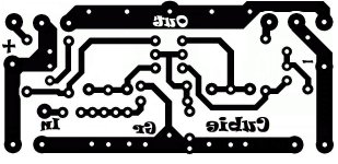
Thank you!!! I have an even smoother version now. I had not printed it out actual size. If 25mmX65mm is correct, this thing is tiny!!!!! Man, drilling it will be some precision work. Bought a 4x6" piece of fr4 on Ebay. I can screw this up repeatedly and not run out of board. Lats are on order. I have the jfets. WhooHoo!!! This is fun. Thanks, Juma!
I couldn't believe just how small this thing is, so I took a laser print downstairs, and what do ya' know, the pin spacings on the pots and the semis are correct. This guy is so unbelievably tiny.
I'm going to try and stop messing with the traces now. Type would have to be modified for a divided board. Not going to divide the board.
Looking good, Cambe!!!
Type would have to be modified for a divided board. Not going to divide the board. Looking good, Cambe!!!
Attachments

Last edited:
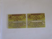
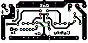
Be careful you have 2PC of Pc board together!
You have to dived into two piece so you writing in wrong place also you have to mirror imaged.
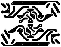
My lay out for these fantastic little amp!
Only post that so you can see 🙂
It need to be resized at print out.
Greetings
You have to dived into two piece so you writing in wrong place also you have to mirror imaged.
My lay out for these fantastic little amp!
Only post that so you can see 🙂
It need to be resized at print out.
Greetings
Attachments
Both channels are identical, one is rotated 180degrees from the other. I plan to build it so the lats stick out from each side. As I posted, I am not intending to divide the board. The layout is per juma's post, which says it is copper side view. So no mirroring should be necessary, unless I do a laser print transfer. I could easily arrange them side by side, so the lats would be in a row. Now that I realize how small this is, I may decide to do that. Nice layout!
Last edited:

Lovely.
Starts to look like a human was involved in the design/layout process, instead of being ruled by machines
Starts to look like a human was involved in the design/layout process, instead of being ruled by machines
And maschines was created by who, Martians..Lovely.
Starts to look like a human was involved in the design/layout process, instead of being ruled by machines

Vule, please don't spoil this rare philosophical moment - let us indulge in its revelational depths... 😀
Last edited:
A Big round project Mr Juma
I like it very much, thanks for share and inspire newbie people like me.
I like it very much, thanks for share and inspire newbie people like me.
- Home
- Amplifiers
- Pass Labs
- Cubie - small F5 variant with GR grade JFETs and LatFETs