I's comforting to know that there was someone who enjoyed his time here... 😀.... Thanks for bringing that up
I still don't know how the room will look in the end - furniture delivery time is very long here (5-10 weeks) and we didn't yet made a decision what to buy...Suggest you ...
Answering that question will destroy this thread, so please open a new thread with the same question - there's a can of nasty worms behind it... 😀Whats wrong with transformer ? mind to share.
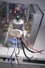
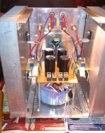
Since it's been decided that a small LU1014 based circlotron will be built and I need a 4 secondary transformer for that project, Cubie got a whole new PSU - a Sedlbauer 200VA potted toroid (2 x 15V secondaries) followed by a IRFP044N based cap. multiplier. It's on since yesterday and the change is not big, although noticeable - the presentations is a bit more cleaner and more defined (noticeable in big orchestral recordings) with a same gentle overall signature. So, it can be considered as an upgrade.
Here is the sch. and a couple of pics (big 0R1 ceramic resistors in the negative power rails are there just to check the bias current - they were removed after the measurement):
Here is the sch. and a couple of pics (big 0R1 ceramic resistors in the negative power rails are there just to check the bias current - they were removed after the measurement):
Attachments

Since it's been decided that a small LU1014 based circlotron will be built and I need a 4 secondary transformer for that project, Cubie got a whole new PSU - a Sedlbauer 200VA potted toroid (2 x 15V secondaries) followed by a IRFP044N based cap. multiplier. It's on since yesterday and the change is not big, although noticeable - the presentations is a bit more cleaner and more defined (noticeable in big orchestral recordings) with a same gentle overall signature. So, it can be considered as an upgrade.
Here is the sch. and a couple of pics (big 0R1 ceramic resistors in the negative power rails are there just to check the bias current - they were removed after the measurement):
Hi Juma,
As I am currently building a Cubie, and my trafos are 15+15, cap multiplier was already planned. I noted from the various schematics of cm you published that you used MOSFETs alone, while when you used BJTs they where in Darlington arrangement. Would a MOSFET (IRFP240 / IRFP9140) be used instead of 2sc5200/2sa1943 in the schematic in post http://www.diyaudio.com/forums/pass-labs/243592-vfet-pp-amp-8.html#post3770301 ? Is it beneficial instead of simple MOSFET?
Thanks
Guido
I don't know what you mean by beneficial - what do you want to achieve with BJT-driven-MOSFET-arrangement ?... Is it beneficial instead of simple MOSFET?...

I don't know what you mean by beneficial - what do you want to achieve with BJT-driven-MOSFET-arrangement ?
As far I understand, "the capacitance appearing at the base of the output device is effectively multiplied by the gain of the device" Capacitance Multiplier Power Supply Filter thus a hi-gain device (a Darlington or transistors connected in a Darlington pair) seems to be more efficient (in terms of ripple reduction) than a simple one with lower gain (a single MOSFET).
Actually you do used two BJT in a Darlington arrangment, http://www.diyaudio.com/forums/pass-labs/243592-vfet-pp-amp-8.html#post3770301, my though was whether a BC550/560 driving the base of IRFP240/9240 is wortwhile at the expense of the greater complication (with the obvious changes to the schematic).
I'm trying to understand, rather than simply copy-paste...
Many thanks,
Guido
If you decide to drive the MOSFET with the BJT you'll get a few dB more of ripple rejection and somewhat better freq./phase response (both at high frequencies, out of audio band) at the cost of 1-1.5V lower output. I don't consider it worth the trouble but you can make an experiment in context of possible hearable improvement. Take care to polarise correctly the BJT because there is no current through MOSFET's gate (except for charging the gate's capacitance)...
2 J74GR in parallel for regular F5
I found genuine K170BL but only J74GR
Is it possible to use 2 74GR in parallel for example 4 + 4 mA Idss and one 170BL of 8mA for the input of the regular F5?
If the transconductance of the 2 74GR in parallel is higher than the 170BL it could be possible to degenerate with higher source resistor...
But then how to calculate the resistor, and what value of Idss?
In parallel configuration, do the 74GR need to be matched?
Paralleling the JFETs is ok. They don't have to be matched - just take care that each has its own Rs that will equalize the Id of paralleled JFETs and make the sum of two Ids apprpximately equal to k170's Id.
paralleling 2 j74 will increase the transconductance of the resulting fet?
How to use separate source resistors if the feedback has to go in that common point?
How to use separate source resistors if the feedback has to go in that common point?
Yes, and ... ?paralleling 2 j74 will increase the transconductance of the resulting fet?
Obviously, every Rs will have to have two parts. If you think so much about gm, you'll have to equalize it somewhat, and provide the feedback point too.How to use separate source resistors if the feedback has to go in that common point?
ok then I will use the degeneration technique of EUVL for the F5X:
for one J74 with about 0.8mA higher Idss an extra 5ohm are needed on the source to equalize the higher gm of the j74 to match the k170
but on my case with 2 J74 in parallel, what extra source resistor do I need?
And should the Idss of the 2 combined j74 still be 0.8mA higher or maybe more?
I don't know how to calculate this, it is over my skills but if someone helps me? Maybe EUVL?
I think that it could be useful for other DIYers to use j74GR for the F5...
Measure them and calculate. Think like this:.... but on my case with 2 J74 in parallel ...
Attachments
Last edited:
I have a nice 15V 240VA transformer witch (unfortunately) already center taped like these 15V-0-15V
Can that transformer be used somehow with these power supply 🙄
Based on JUMA feedback these PS is improved the sound of the amp I would love to build it that way to.
Any advise welcome
To purchase a new transformer is a waste of money since I already has these
The nearest I have with dual secondary that would be 2X 20V-0 650VA, that really over kill for these amp and the Voltage way to high to much power to burn away.😱
Greetings Gabor
Attachments
- Home
- Amplifiers
- Pass Labs
- Cubie - small F5 variant with GR grade JFETs and LatFETs