Hi ppy
I saw new project I put the post here at firs by mistake... I wil copy to new topis sirry...
I saw new project I put the post here at firs by mistake... I wil copy to new topis sirry...
Last edited:
I can only say that CT is at the very top! This is what I sucesfully done. It have four optic inputs, one analog input, one usb input, fm radio, bluetooth, rpi as a media server or whatever, Hypex power modules. Transformers will be replaced soon with opamp based i/v, ina849 to convert diff to single ended, than multi feedback lpf, than resistor lader based i2c tone control, than single ended to diff at the end. Some vids how it sound
Attachments
Last edited:
great job, CT7302 isn't bad at all.I can only say that CT is at the very top! This is what I sucesfully done. It have four optic inputs, one analog input, one usb input, fm radio, bluetooth, rpi as a media server or whatever, Hypex power modules. Transformers will be replaced soon with opamp based i/v, ina849 to convert diff to single ended, than multi feedback lpf, than resistor lader based i2c tone control, than single ended to diff at the end. Some vids how it sound
if you spend a lot of time studying it, thanks for your work

We are working now on totaly diferent design, in short explanation it will contain no dac at all, instead PDM modulated class D with variable voltage at H ganFET bridge as a volume control, it will be in short explanation an true power dsd dac with full resolution even at low volume level 🙂
If that succed the next plan is study on http://dafx.de/paper-archive/2004/P_372.PDF , that way we would not have need for analog equaliser, instead direct dsd equalisation for realy true dsd power dac.
If that succed the next plan is study on http://dafx.de/paper-archive/2004/P_372.PDF , that way we would not have need for analog equaliser, instead direct dsd equalisation for realy true dsd power dac.
Last edited:
I can only say that CT is at the very top!
Not sure what you mean by the very top? Top of the sample rate converters? Top of the PCM->DSD converters? Something else?
https://png.pngtree.com/element_our...etition-podium-illustration-image_1449476.jpgNot sure what you mean by the very top? Top of the sample rate converters? Top of the PCM->DSD converters? Something else?
Yes, booth is ok but CT is in my opinion better and in the same time have more features. I am always against collective opinions driven by marketing opinions. What I hear is crucial to my conclusion and I doesn't pay attention to what others say, so it's redundant...
Last edited:
There are plenty of that online and on this forum.I am always against collective opinions driven by marketing opinions.
Seems to me CT7203 loses the SQ competition compared to AK4137. I tried both of them, did you?
Both CT7203 and AK4137 do a/ pcm to pcm sample rate conversion b/ pcm to dsd format conversion and c/ jitter attenuation through the normal necessary functionality of an ASRC bridging two clock domains.Yes, booth is ok but CT is in my opinion better and in the same time have more features. I am always against collective opinions driven by marketing opinions. What I hear is crucial to my conclusion and I doesn't pay attention to what others say, so it's redundant...
Each chip may be better or worse at any of these functions and there is no jitter attenuation data given for either chip.
Mark when you tested these two sample / format converters, were they burdened with attenuating any jitter or were the I/O clocking streams synchronous and the I stream low jitter?
TCD
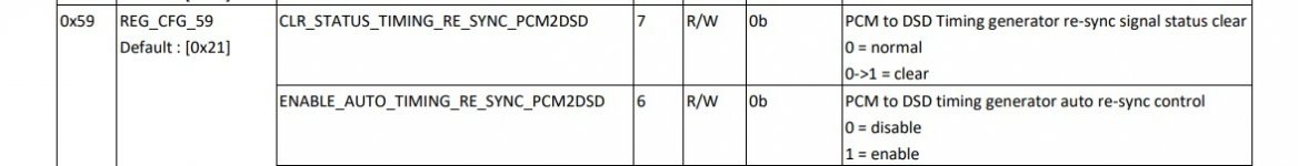
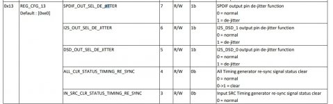
CT have dejiter and resync functions, and a lot of fine tunning for master clock output, you should take a look at einchoria pdf file. Here is some of the functions, see picture. Few diferent src mode, synchornous or asynchronous with a lot of tunning parameters. Also it have sample rate detection and in the same time interupt pin which you can use for example to switch between two diferent clocks domains, many more other things with a lot of possibility and combinations. Three i2s inputs, 5 spdif inputs, 1 spdif out, two or three if I'm not wrong i2s outs, so in comparation to AK it have a much more functions. Also take a look at THD and SNR! The price-features ratio against the competition, you can agree that it is quite decent and ic is not bad at all. The only bad against CT is that CT do not have strong marketing as AK and competition.
Attachments
Last edited:
@Terry Demol
Just sent you some info on the subject by email. Its more than I can share publicly.
For forum readers, some preliminary comparison of SRC4392, AK4137, and CT7302PL was done for upsampling and conversion to DSD. The target dac was an AK4499 evaluation board which includes its own AK4137. External to the dac board were SRC4392 and CT7302PL on factory evaluation boards. The was also an external ebay AK4137 board modified to clean up power to the AK4137 chip. The external boards were fed I2S from a low jitter USB board. For reference, upsampling and or DSD conversion could also be done in HQ Player.
The AK4499 dac evaluation board clock was used as a reference clock for the external ASRC boards. The USB board was using its own clocks. The test configuration was like:
PC-> external ASRC board -> AK4499 eval board (with or without using the onboard AK4137 for DSD conversion).
The purpose of the comparison was to help pick out a prospective set of upsampling and DSD conversion chips for further development in the form of a custom PCB with fully synchronous clocking, including an interface for a synchronous (externally clocked) USB board.
Ranking of the chips for upsampling ended up as follows:
1. AK4137
2. SRC4392
3. CT7302PL
Ranking for DSD conversion was:
1. AK4137
2. CT7302PL
Both AK4137 and SRC4392 were deemed useable. CT7302 was deemed unacceptable for use after multiple trials and consultations with Comtrue. The last email I sent them on the subject contained the following summary:
Hi xxxxx,
Sorry to hear you say that CT7302 performance is not sensitive to power quality for the pll or other sections.
I know that AK4137 is audibly sensitive to power quality, and so is SRC4392. On the SRC4392 evaluation board there is a jumper wire in series with the pll power pin that is shown on the schematic as an RC filter on that pin. The jumper wire is in place of the undefined R value resistor. Using an ultra-low noise LDO regulator for that pin audibly improved sound quality to some extent. For AK4137 replacing a low cost LDO 3.3v regulator with an TPS7A47 regulator resulted in a very substantial audible improvement in sound quality.
In the case of CT7302, I first listened to it using a very low jitter USB to I2S board which also has a master clock output available. Using the dac chip on the CT7302 evaluation board, I used the onboard MCU to set the sample rate to 352.8kHz, then removed the I2C jumpers and used an Arduino to set the SRC mode to 2 (using the MCLK from the USB board. Even in that configuration, the dac chip sounded best with no upsampling. With CT7302PL upsampling it sounded more distorted.
I then attached the I2S0 output of the CT7302 board to the I2S input of an AK4499 evaluation board and used a 25.4Mhz ultra low jitter MCLK as the reference clock for CT7302 SRC mode 2. In both DSD and I2S output modes CT7302 sounded much more distorted verses the sound quality of AK4137.
Given the experimental results so far I was hopeful you could provide some guidance as to what I might try to improve CT7302 sound quality.
Another thing that some of us who develop dac designs have noticed is that although in theory I2S jitter should not matter since I2S data relatched by MCLK inside a dac chip, there is still some some effect on sound quality if the I2S signal is jittery. Could be there is some stray coupling of the jitter inside dac chip, don't know what the exact mechanism is.
One other thing we noticed is that some of the distortion that is audible is non-time invariant in the sense that not all of it shows up on an FFT using J-Test as a metric. Presumably the distortion is modulated by noise or by some asynchronous signal thus making it more difficult to detect in FFT measurements.
Again, I am sorry to tell you about my less than hoped findings so far. I have provided some other information about testing and listening observations in previous messages that I hope may help you understand how some of your other prospective customers will likely be evaluating your product. Don't know if the information will be of any use to you or not, but I will take the chance to offer it just in case it can be of help.
If by chance anything does occur to you that I might try to experiment with to improve sound quality I would be very interested to learn what it is. Otherwise I think I must pass on CT7203 and convey my findings to some other people as one person's opinion. There is much interest in the chip by some audio designers and I'm sure some will want to try the chip themselves to see if they agree with me or not.
Best Regards,
Mark
EDIT: In addition to my correspondence with Comtrue, I later heard from professional dac designer John Westlake. He was looking for an AK4137 replacement after the AKM fire. He wanted to know if I ever got CT7302 working satisfactorily. I told him about what I tried and my communications with Cometrue. John said he had some things he wanted to to try to see if he could get CT7302 sounding better. He said he would let me know if any success. Never did hear back from him after that.
Last edited:
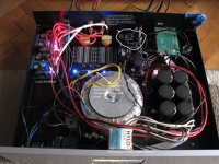
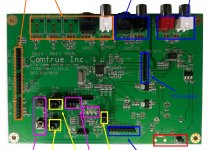
My first board with CT7302 had problem with distrortion, it was related to i2s traces which was not shielded, and end of traces was with 2.54 pin headers, those pin headers caused distortion. Seccond board was at 4 layers, i2s lines is fully shielded between layers and end off traces is u-fl now. Now CT sound very good. I do not have CT evolution board but custom board maded by myself, DC is preregulated with LM than regulated with LT3042, booth 3.3V line and 1.2V line on CT and the rest of system. Ground plane fully isolated from any analog circuit, picture 1 post 42.
Last edited:
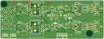
Pic attached below of CT7302 eval board I have. Surface routing of I2S inputs is not that different from external AK4137 and SRC4392 boards. Have seen a problem before where tin pin header surface corrosion increased jitter. Using gold pin headers solves the problem. Pin headers on my CT7302PL board are tin. Have also seen power supply quality to ASRC chip have some influence, which Comtrue denied could be an issue for their product.
Attachments
Last edited:
First of all to make this clear, It's not my intention to advertise any brand, I'm just saying that I'm very satisfied with CT. Those 2.54 pin headers is causing distortion for sure, at least I have noticed that when I connected Amanero to CT, it was noticeable on ear. Than I added some alu foil over it and imediatelly noticed something better. Decided to make another design by shielding i2s traces completelly and removed any pin headers in trace, and finaly it working now satisfactory. It seems CT is very sensitive to external influences. Notice how long traces you have between pin header and CT!
Regarding noise sensitivity, did that occur in proximity to your PDM modulated Class-D power dac? Or away from known sources of EMI/RFI?
One more interesting thing about when I had i2s traces unshielded, the neighbor's air conditioner was interfering with it which I hear on my speakers, so definitelly relation to CT and i2s traces, I have noticed it definitelly and definitelly all that things disapeared after shielding i2s traces
Edit:
New design is on P2 Propeler or maybe on an GPU, no CT at all.
Edit:
New design is on P2 Propeler or maybe on an GPU, no CT at all.
Even having CT on isolated plane was not enought, finaly fixed things by connecting our isolated gnd plane trought 100nF to ground lift star
Not too surprising. I find improvement by putting test boards in an emptied out steel file server case for shielding. Clock and DSP board ground plane faces adjacent dac board ground plane. Audibly less radiated EMI/RFI coupling between the boards that way than if component sides of the boards face each other. Some people don't believe it when told the lengths necessary to go to for best performance.
4 layer pcbs the most have a lot of via, and I'm looking to make always single pcb where all that vias is towards the bottom panel of the device, that way there is less chance for interference trought vias. Additionally I'm thinking about mu-metal shielding some of the important circuity like on this picture https://hollandshielding.com/content/LC/Large-clip-for-PCB-shielding-cans-big-web.png
Last edited:
- Home
- Source & Line
- Digital Line Level
- CT7302PL