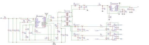
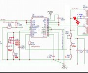
All the things is fully isolated including gan half bridge, this is reason why we have chosed MAX17687 iso buck to supply gan half bridge iso ic's, 2x12V is for bootstraping on gan half bridge and 5V is for iso ic things, problem is only MAX17867 which is unable to stabilise. Compensation at pin COMP on picture 1 might be wrong because on simulation on Maxim site we have made compensation network like on picture to stabilise some things in simulation but on real circuit we found it wrong and calculated new compensation network, its now like on picture 2, that way its more unstable, I can hear hiss and MAX is hot very fast, so I have changed compensation network as per eval board schematic, nothing helped. Also I have tried 1nF between iso gnd and pgnd, even it not helped, realy have no idea whats wrong with it. HV is +-46V from Hypex SMPS400A180 . Half bridge is not soldered and all 3 regulators have no load so we added some load resistors over condensers to make enought load for MAX to not have "skip" active
Attachments
Last edited:

Didn't tried, problem is stabilising Vprim<->gnd (figure 9 capacitor C8), there we doing Vprim measurement. Between LX,->gnd there is some small oscilations but square wave is quite regular in shape, strange that I can hear hicup while regulator is at 500khz and COMP calculated to match that frequency (picture 2 from prev post), and MAX is prety fast hot, and also square wave between LX-GND show irregularity. VPH2 is declared and wold not have problem with 500khz, MAX too, also all condensers is all >100V, realy have no idea. I will try one more time tommorow, now regulator is working with RT=100k, about ~200khz, will try to add r+c to iso gnd directly to earth maybe Hypex SMPS gnd is not good enought. Also snuber on secondary migh be a solution, let see! Thank you!
Attachments

Last edited:
Without having the schematic handy, with test points labeled for each scope pic, and with camera pics of how the probes and probe grounds are connected to the DUT, its not all that obvious what we are looking at. Also, with this kind of circuitry it matters to check out ground noise and or radiated noise to see if they are affecting measurements in some way.
IOW, if there are problems that are not getting solved easily, then it can help to go over everything in a very meticulous way to make sure no problems are being missed at each stage of troubshooting.
IOW, if there are problems that are not getting solved easily, then it can help to go over everything in a very meticulous way to make sure no problems are being missed at each stage of troubshooting.
Schematic is in post 101 ! Seems iso transformer have not enought energy, not enought uH ?? I will try to change paralel connection of the two primar to serial connection, that way it will have ~46uH (11,6uH * 2primar^2 = cca46uH), 2:1:1:1:1, Isat max 1A peak, delta_Iprim 0,4...0,5App, Vprimar need to be changed to cca 31,5VDC, frequency will stay the same 500khz, Duty = Vprim/Vin = 31,5/47 = cca 0,65 ( 65%, almost at the border of the duty cycle ), and compensation network will be like this for test:
R43 = 1100* (fsw/20){ Cout(1-D)K^2 + Cprim} = 30K (27K...33K)
C47 = 100 / (PI*Fsw*R43) = 470pF
C19 = 22pF
A lot of work! Is it worth to try? Any idea?
R43 = 1100* (fsw/20){ Cout(1-D)K^2 + Cprim} = 30K (27K...33K)
C47 = 100 / (PI*Fsw*R43) = 470pF
C19 = 22pF
A lot of work! Is it worth to try? Any idea?
Last edited:
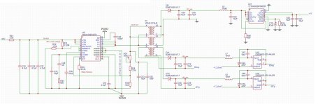
Biger schematic and also changes from post 105 which I want to try! Dummy load resistors 4.7k is allready soldered over C54, C55, C73, C74, C58, C59, C62, C61, C64, C70, enought to keep iso buck in enought load
Attachments
Last edited:
Just a thought: This might be easier to troubleshoot if you had a scope current probe.
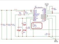
Lacking that, fig4. of MAX17687 datasheet shows charging current waveform of the transformer is a ramp (when QHS is on). If so charging current of C52,C53 must be a ramp. Voltage waveform on caps should then be the integral of that. If transformer inductance drops as flux increases then current waveform will no longer be a ramp, so capacitor voltage will be distorted from ideal. Not nearly as nice as a more direct measurement.
Lacking that, fig4. of MAX17687 datasheet shows charging current waveform of the transformer is a ramp (when QHS is on). If so charging current of C52,C53 must be a ramp. Voltage waveform on caps should then be the integral of that. If transformer inductance drops as flux increases then current waveform will no longer be a ramp, so capacitor voltage will be distorted from ideal. Not nearly as nice as a more direct measurement.
Yes, according to datasheet secondary inductance should be about 30uH.Seems iso transformer have not enought energy, not enought uH ??
This should work better but maybe VPH2-0216-R could work with the original schematic with lower Vprim.I will try to change paralel connection of the two primar to serial connection, that way it will have ~46uH (11,6uH * 2primar^2 = cca46uH), 2:1:1:1:1, Isat max 1A peak, delta_Iprim 0,4...0,5App, Vprimar need to be changed to cca 31,5VDC, frequency will stay the same 500khz, Duty = Vprim/Vin = 31,5/47 = cca 0,65 ( 65%, almost at the border of the duty cycle )
I will try to lower Vprim voltage, thanks! This looks much better now but still not very good.
All the changes I have done:
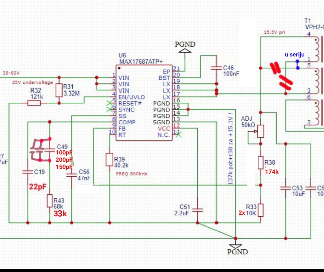
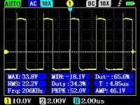
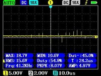
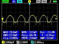
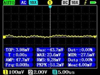
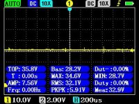
Vprim measured at C52:

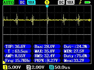
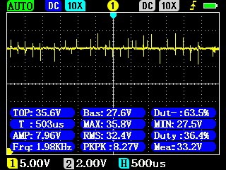


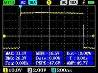
Now between LX and PGND:
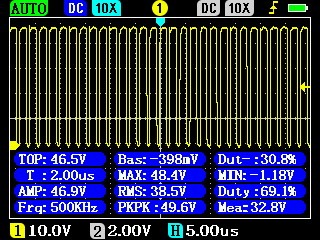
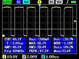
What need to be done to solve the rest of noise at Vprim? Any idea?
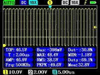
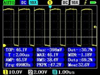
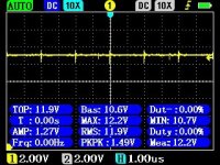
Linear regulator top one (float1 12V), this one manifest the best noise, bottom regulator is better and 5V regulator too but still have some noise, top regulator have more noise. (I am verified by an external regulator to connect/replace iso buck function and verified that top regulator do not have problem, and also not have noise, so problem is definitelly iso buck!) Top regulator looks like this:

All the changes I have done:
Vprim measured at C52:
Now between LX and PGND:
What need to be done to solve the rest of noise at Vprim? Any idea?
Linear regulator top one (float1 12V), this one manifest the best noise, bottom regulator is better and 5V regulator too but still have some noise, top regulator have more noise. (I am verified by an external regulator to connect/replace iso buck function and verified that top regulator do not have problem, and also not have noise, so problem is definitelly iso buck!) Top regulator looks like this:
Attachments
-
 003L.jpg39.4 KB · Views: 352
 -
 002L.jpg44.1 KB · Views: 366
 -
 001L.jpg41.4 KB · Views: 667
 -
 006.jpg39.8 KB · Views: 350
 -
 004.jpg39.2 KB · Views: 351
 -
 003.jpg38.9 KB · Views: 363
 -
 002.jpg39.6 KB · Views: 354
 -
 001.jpg39.3 KB · Views: 361
 -
 000.jpg38 KB · Views: 350
 -
 2023-06-07_175937 (1).jpg78.9 KB · Views: 385
 -
 000R.jpg39.7 KB · Views: 345
Last edited:
May I ask how you are checking for ground noise in the above measurements? Is it according to the methods described in pages 46-54 of the attached? Just checking is all, since we can't be there to see how you are doing it. No offense intended by asking.
Attachments
No ground isue here, I have other circuits which do not have noise, gnd is only one point, the same which I am using all the time! Osciloscope is not maybe very good and very precise but enought to show whats going on, in this circuit definitely something is missing, not osciloscope related.
Last edited:
Okay. If not having read about advanced probing recently, its always a good refresher. Ground lead can act like an antenna for radiated switching noise, etc. Highly recommended for anyone following the thread who may not have studied the subject matter.
Yes I will check that, thanks! I'm using spring on probe but can't use on every circuity, for example can't connect it between LX and PGND and must use default probe gnd aligator cleme, but even spring on C52 or aligator cleme didn't change things much here, almost no diference!
Last edited:
What I didn't checked is earth pin of the Hypex SMPS, how it is internaly made. I have connected SMPS trought that pin to my earth. So now signal pgnd from the smps power rail is the main ground for the rest of circuity. Might be that ground is not good? I didn't checked how MAX will behave with an linear power supply, I will check that soon!
Could be it is noisy, or that there is radiated noise in the vicinity. One check is to connect the scope ground lead to the DUT, the touch the probe tip to that same ground point and see if the scope shows any signal. It is does show a signal then there is a noise pick-up issue to investigate.
Markw4 you're right! Ground noise when smps is on! My earth is connected to J7 pin of the SMPS
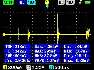
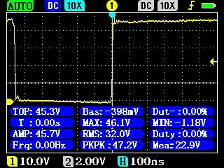
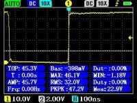
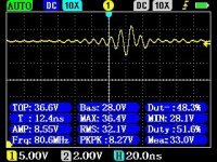
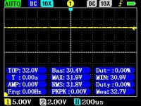
When I add 1nF directly from PGND (at C52 point) to EARTH this is a result at Vprim(C52), noise fixed!
Vprim now:

When I add 1nF directly from PGND (at C52 point) to EARTH this is a result at Vprim(C52), noise fixed!
Vprim now:
Attachments


Last edited:
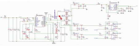
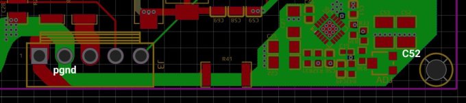
Hm but this is strange! SMPS400A180 connector J7 is allready trought 100nF connected to earth! My earth is connected directly to J7 of the SMPS. Our DDPD power ground is allready connected to J3 connector of the SMPS, Also C52 is connected with one side to the same PGND, so whole DDPD share the same PGND of the SMPS, than whats going on? Why 1nF connected at C52 pgnd point to earth fixes isue? As you can look at picture C52 is allready on pgnd! Whats going on here?
Attachments
Last edited:
There are trace inductances, capacitances, and so likely various impedance peaks and nulls. Call them resonance modes if you like. You must have created a structure that has a null at the noise frequency.
Part of what is involved is that ground is not exactly a disposal hole for noise. Energy still has to be dissipated somewhere, or maybe not be allowed to build up in the first place.
Part of what is involved is that ground is not exactly a disposal hole for noise. Energy still has to be dissipated somewhere, or maybe not be allowed to build up in the first place.
Thanks Markw4 ! Might be isue with earth cond at J7 pont on SMPS! Some days ago when I measyured SMPS, do not have much load right now only at MAX17687 and the rest of regulators, and I thinked maybe noise is because of not enought load, found some not that small noise on them, earth point at J7 connector looks like not working, might be that 100nF condenser is not ok! I will check them. Smps is bought new, strange.
- Home
- Source & Line
- Digital Line Level
- CT7302PL