I'm with you on the cage / clear case with ventilation SS, definitely not okay with the HV exposed. Interested to see how your Eimac caps turn out, I was able to hunt down some HR2 sized caps, should work for the 3C24. No idea what will come of this but fun to mess around with these transmitting tubes. I found a cheap pair of HK54 as well, 3C24s big brother.
I have been thinking over some ideas on my 801A A2 amplifier. I was using a source follower FET before with plans to get a 0V bias point using a DC regulated heater supply for the EF37A, making the gate of the source follower FET a few volts positive by taking a tap from the regulated heater supply. I tried this out with a filament supply I had laying around maybe two months ago with mixed results. I'm sure I could improve upon it, but I'm not loving the idea.
I am considering dropping the source follower and going with a 6BX7 cathode follower with a current sink instead, like below. Adjustable LND150 CCS sets the grid voltage on the 6BX7 so the cathode can be adjusted easily to both sides of 0V to dial in a perfect 60mA bias on the 801A. I like it!
Other thing I would like to experiment with is using a VR105 voltage regulator tube to get 105VDC on the EF37A screens. Won't be as robust as the feedback mechanism in the schematic above, but drift has not been an issue for me so far even without it, which I attribute to leaving the EF37A cathodes unbypassed - open loop gain is not as crazy high as some of the other CCS loaded pentode stages in this thread. We'll see how it goes!
Looks like some interesting things to try!
Here's how the caps are turning out. Pretty huge, and heavier than the tube. In the application these tubes were designed for, the anodes were inserted into a larger metal structure, so I may have some structural support (made of an insulator) on this anode cap. I don't like the idea of putting a bunch of weight on the anode glass/metal seal. I'm still working out how I'm going to mechanically support this thing.
The transmitter tubes are fun to play with and if you get the right ones, can be had for a decent price.
I didn't really have pentode plate drift problems until I cranked gain up over 1000. Of course, the plate voltage was stable over a couple of hours. I don't know what would happen over months.
Attachments

Recently I've been playing a while with the EF37a. A beloved pentode which I used extensively in the past. The results are here:
Mono Amp: EF37a driver (part II) – Bartola(R) Valves
As discussed with JC Morrison, setting the screen voltage to the right sweet spot is key to minimise distortion of the driver stage. I found it around 115V for an anode voltage of 235V. The DC feedback is key to avoid drift in my opinion.
Ale
Have you tried biasing G3 to to try to square up the knee of those curves? If they could be squared up a bit, I'm sure distortion could be lowered (at the expense of a sharper clip when/if you were to clip).
Recently I've been playing a while with the EF37a. A beloved pentode which I used extensively in the past. The results are here:
Mono Amp: EF37a driver (part II) – Bartola(R) Valves
As discussed with JC Morrison, setting the screen voltage to the right sweet spot is key to minimise distortion of the driver stage. I found it around 115V for an anode voltage of 235V. The DC feedback is key to avoid drift in my opinion.
Ale
Hi Ale - thank you for the write-up, I read JC Morrison's article per your recommendation some months ago, as you can see I have implemented his DC feedback circuit on the EF37A using the DN2540. I think this will be in my final design, have to breadboard the circuit one more time, much appreciated for pointing me in that direction.
Here's how the caps are turning out. Pretty huge, and heavier than the tube. In the application these tubes were designed for, the anodes were inserted into a larger metal structure, so I may have some structural support (made of an insulator) on this anode cap. I don't like the idea of putting a bunch of weight on the anode glass/metal seal. I'm still working out how I'm going to mechanically support this thing.
Very nice! Certainly have more surface area than the Eimac originals. Maybe you could suspend them from the cage with some non-conducting material?
Have you tried biasing G3 to to try to square up the knee of those curves? If they could be squared up a bit, I'm sure distortion could be lowered (at the expense of a sharper clip when/if you were to clip).
Hi, great suggestion, haven't tried it. Perhaps will fire up again the curve tracer and test there G3 voltage impact. Any suggestions?
Thanks
Ale
Hi, great suggestion, haven't tried it. Perhaps will fire up again the curve tracer and test there G3 voltage impact. Any suggestions?
Thanks
Ale
I just remember looking at smoking-amp's curves for various types and noticing that small G3 bias could have remarkable effects on the curves. +12V on GU-50, for example, gave sharp knees to the curves and made them look like 6L6 curves.
If you have a curve tracer and a variable +-15V supply to vary voltage to G3, you could get a really clear idea of whether this will help things or not.
Hi, great suggestion, haven't tried it. Perhaps will fire up again the curve tracer and test there G3 voltage impact. Any suggestions?
I posted in this thread earlier some screenshot of my Gubernator-71 amp that shows that. ;-)
Thanks for pointing me in the right direction, good reading. I remember few times back in time when Anatoliy mentioned the use of +12V on the GU50 G3.
Will experiment....
Will experiment....
In attachment some of the GU50 curves at different voltages on g3.
I downloaded them from Anatoliy's forum when it was still available online and I was looking to design a bass amp with them.
You can see how curves square up and screen current goes down at the same time, while increasing the voltage on g3 (up to a point).
Has anyone ever tried with a EL34 or EL84? Will they have a similar behaviour?
Will it square up the curves in UL too? (I know none of you is an UF aficionado)
Attachments
Last edited:
In attachment some of the GU50 curves at different voltages on g3.
I downloaded them from Anatoliy's forum when it was still available online and I was looking to design a bass amp with them.
Thank you for saving them! Since I am moving, I had to shut down the server in my barn, and move the content to the cloud. I am afraid, the forum had been lost. :-(
I'm really sad that your forum has been lost, it was full of useful informations and ideas.
I can search if I can find some more data I downloaded and PM to you, if you like.
I can search if I can find some more data I downloaded and PM to you, if you like.

Thanks for pointing me in the right direction, good reading. I remember few times back in time when Anatoliy mentioned the use of +12V on the GU50 G3.
Will experiment....
I did some quick test and was happy to see easy and quick improvements by squaring up the pentode curves. I played before a while looking at the FFT to optimise the screen bias setting so not sure if there was too much room for improvement in this case. Nevertheless, I was happy to see shelving distortion by 0.1% at 200Vpp on the driver. The harmonic profile can be tweaked slightly as the curves get squared up between 12 and 16V in the case of the EF37a.
Here is the write up and some pictures:
Mono Amp: EF37a driver (part III) – Bartola(R) Valves
Cheers
Ale
Perfect timing for an upcoming project, thanks! Curves as a single pdf attached.In attachment some of the GU50 curves at different voltages on g3.
Attachments
I've got some new 40W output transformers on order from Jack at Electra-Print.
I'm going to pair these with 327-A and 100TH and see how things go.
End goal is to build an amp that will accept 826, 327-A, or 100TH with some simple reconfiguration (less than an hour of work or so).
826 will run at ~540V and ~105mA. 327-A and 100TH will run at ~750V and ~125mA. I'll probably be able to get over 20W output with the 826 and 35W or more with the bigger tubes.
I'll also design a solid-state ripple-rejection circuit for the B+ that's good up to some pretty high voltages. I don't want to make it regulated per se (in fact, I'd rather it not be so that pass device dissipation doesn't vary much with line voltage), but I do want the ripple gone.
That's what I plan on chronicling in the next months in this thread.
I look forward to your build. Wonder how a capacitance multiplier does at high voltages?
I imagine it'd do fine as long as the parts are up to the task, and that's kind of what I'm imagining. I picked out one of the new IXYS linear HV fets to start experimenting with, but it is backordered.
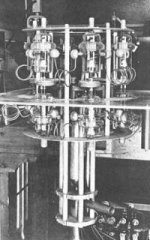
What's taking up all of my time right now is building the structure to hold the 327-A. I was able to stuff the filament leads into a tube socket and test with some alligator clips and a plate cap that wasn't the right size to determine that the tubes were usable, but I have to do something better if I'm going to use them for any length of time. I have one that was just a little gassy to start with that I'd like to run for several hours but I don't feel comfortable doing that until I'm all set up with something that is mechanically sound and will keep the leads cool.
AudioXpress (or maybe GA?) had an article about making sockets for pins. Although you need a mini lathe and mill to do it.
AudioXpress (or maybe GA?) had an article about making sockets for pins. Although you need a mini lathe and mill to do it.
I'm making plate/grid caps out of LED heatsinks and that only leaves the filament leads (10.7A current) that come out the bottom. I looked at 38999 contacts and unfortunately the filament leads are right in between sizes. I can't use heatsinks or even the old Eimac caps because the leads are too close together. I'm just drilling 1/2" aluminum rod and tapping a hole for a set screw to clamp down on the filament leads. It's the best I have come up with so far, but I am a little worried about the high current and I'd like the best contact I can get.
- Home
- Amplifiers
- Tubes / Valves
- Corona: An Ultra-Low Distortion A2 DHT SE Amp Prototype