looks like there is expansion as the plate gets pulled lower at least at first, then it starts compressing later. Are you getting 2nd harmonic dominant behavior at lower levels?
In previous real-world measurements no, with plate to cathode feedback seeing a lesser 2nd with higher 3rd harmonic. Using a resistive load on the EF37A as opposed to the CCS yielded a dominant H2, but that is expected. Current simulations I am running (which of course, may not be accurate), are showing a similar H3 dominant spectrum with increasing H2 at higher outputs, but never H2 dominant.
I've seen this a few times in my own circuits, and most of the time, what was happening (I think) was 2nd harmonics were being cancelled leaving 3rd and 2nd at a similar level, then right at maximum power output, 3rd is dominant by a couple of dBs.
So perhaps you are seeing some partial cancellation of 2nd?
So perhaps you are seeing some partial cancellation of 2nd?
Seems like a good idea.Might as well replace that lonely EF37 with a mosfet and be done with it 😀
Attachments
I've seen this a few times in my own circuits, and most of the time, what was happening (I think) was 2nd harmonics were being cancelled leaving 3rd and 2nd at a similar level, then right at maximum power output, 3rd is dominant by a couple of dBs.
So perhaps you are seeing some partial cancellation of 2nd?
Yes, perhaps, I do think it is being minimized on account of the active plate load and cancelled via the feedback loop.
I've been experimenting and have found what I think is an alternative approach that will provide enough gain while maintaining an H2 dominant harmonic spectrum. I am going to experiment with using a high-value plate resistor load and regulating the screen using VR105 glow tube and leave the PMOS buffer on the cathode. Results are good so far in simulation, drastically cut down on the amount of sand in the gain stage 😀

So you have your open-loop distortion, then you have feedback that you can apply to reduce distortion and Zout.
Since the 2nd harmonic distortion in the input stage and the output stage are 180 degrees out of phase, they subtract. If you got really lucky (or unlucky depending on how you look at it) they could completely cancel out, or get really close. That may be happening for you. Then when you apply the feedback, the relative amplitudes stay similar but go down in absolute terms.
When I finished experimenting with the 6384 output tube (similar to 6L6GC), I made modifications to the mosfet driver supply rails and directly subbed in the 826 triode. Despite having less gain with the 826 (and hence less feedback), 2nd harmonic on the output went down like 4.5dB (3rd went down too). It's just that the combo of the 6BN11 and 826 worked out nicely and then the feedback could push the harmonics down together. Note: I've seen the Baxandall chart that shows that higher order harmonics should pop up with increased feedback but I did not see that in my experiments. I have seen some theorize that his chart is only valid for square law devices, which is what he used to make the chart.
I would expect that the resistive plate load and p-channel cathode driver would be a good combo for what you are looking for as long as it gets you to the Zout target you are after. Adding some positive bias to G3 might square up the curves a bit and cut some of the 3rd harmonic from the pentode stage as well, improving your ratio.
Last edited:
Great insight, thanks SS. Seems that finding a pentode / output combination that yields a favorable harmonic profile is important in these A2 designs. One other observation I made was increasing the value of the grounded plate resistor on the CCS-loaded EF37A also reduced H2, which you might expect with further flattening of the load line. I have read in a number of places that NFB increases higher-order harmonics, will keep your observations in mind.
So far, in simulations and from previous real-world measurements, I think using the plate resistor with the PMOS cathode buffer is my next step. Will be some time before I can prototype and measure it, but feel confident this is getting close to the final iteration of this amplifier's design. Would love to experiment with adding some positive bias to g3, just need to come up with a clever way to implement it.
Here is the current schematic, I've attempted to maximize the gain of the EF37A via resistor load. 6BX7 can take a 2.2Meg grid leak which helps, I am going to try a VR105 glow tube to regulate the EF37A screens. They look pretty cool, which is a bonus 🙄
Last edited:
Alright, now I need help!
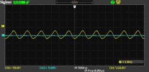
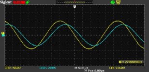
I got my 40W 5k:8 Electra-Print transformers in. I subbed them into the circuit and the amplifier started singing at ~1.1MHz. Not full amplitude, but it is a continuous thing. Transformer is loaded with 8 Ohm resistor load. Yellow trace is output tube plate and blue is secondary.
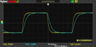
As a quick fix, I put 100 Ohms between the output tube plate and the output transformer and the oscillation is gone. Square waves have no overshoot with the resistor. Obviously, I don't want to add that much series resistance here as a permanent solution, and I don't know yet if connecting a real speaker will provoke further problems.
I'm thinking this is an issue with capacitive loading on a high feedback amplifier and that the solution that works with solid-state amps could work here, an output inductor. I'm just not sure what inductance to target here or if I should just start somewhere and measure results...
Any advice?
I got my 40W 5k:8 Electra-Print transformers in. I subbed them into the circuit and the amplifier started singing at ~1.1MHz. Not full amplitude, but it is a continuous thing. Transformer is loaded with 8 Ohm resistor load. Yellow trace is output tube plate and blue is secondary.
As a quick fix, I put 100 Ohms between the output tube plate and the output transformer and the oscillation is gone. Square waves have no overshoot with the resistor. Obviously, I don't want to add that much series resistance here as a permanent solution, and I don't know yet if connecting a real speaker will provoke further problems.
I'm thinking this is an issue with capacitive loading on a high feedback amplifier and that the solution that works with solid-state amps could work here, an output inductor. I'm just not sure what inductance to target here or if I should just start somewhere and measure results...
Any advice?
Attachments
Ferrite bead with max impedance at 1 MHz? An off-the-shelf device from Digikey worked for my amp.
Ferrite bead with max impedance at 1 MHz? An off-the-shelf device from Digikey worked for my amp.
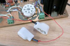
Your comment jogged my memory that I have some 1.5 turn leaded ferrites that I bought a while back and I looked up the datasheet and they are ~80 Ohms at 1MHz. I might give one of those a shot.
Try 100R as grid stopper and 0...few ten Ohm as plate stopper (both carbon comp).
I'd prefer to avoid a grid stopper in an A2 amp unless there is no other solution, since it would be a significant distortion generator.
I think I'll play around with plate stopper schemes, inductive and resistive.
What I'd really like to do right now is alter my dummy load so that it presents some difficult yet somewhat realistic loads to test into. I've read that it is common to put 2uF in parallel with the 8-Ohm resistive load to make sure the amp can handle a capacitive load. I'd like to add something to test inductive loads as well.
I've got a pretty large amount of feedback here for a tube amp so it is time to really assess how stable it is with different loads, and make corrections if necessary.
So far, in simulations and from previous real-world measurements, I think using the plate resistor with the PMOS cathode buffer is my next step. Will be some time before I can prototype and measure it, but feel confident this is getting close to the final iteration of this amplifier's design. Would love to experiment with adding some positive bias to g3, just need to come up with a clever way to implement it.
Sounds like a solid next step. Another idea that just occurred to me is the possibility of adding a nonlinear element in the feedback path that could generate some 2nd harmonic. Something like a diode tube in series with the lower feedback resistor leg. Or maybe an LED. I haven't attempted to predict how big the effect could be with practical parts but it's just a thought I had.
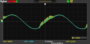
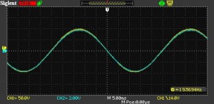
I put the ferrite in place of the 100 Ohm resistor and tried to feel out how this was working. No oscillations without signal. In fact, none until I tried to feel out the lower 3dB point.
I zoomed in on the oscillations on the 10Hz test and they were at about 1.1MHz again.
Sine waves are all at ~1W.
I zoomed in on the oscillations on the 10Hz test and they were at about 1.1MHz again.
Sine waves are all at ~1W.
Attachments
Not sure what’s your latest circuit here but I assume you have the right Frequency comp cap in the FB network?
You may want to add a 10pF cap between anode and g1 of driver
PS. I’m having a nice challenge with the screen DC feedback experimentation and LF gain. Learning experience!
Ale
You may want to add a 10pF cap between anode and g1 of driver
PS. I’m having a nice challenge with the screen DC feedback experimentation and LF gain. Learning experience!
Ale
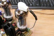
I have learned to slip a ferrite bead or three over the plate lead on any amplifier that uses a tube with a plate cap.
Some tubes, or worse tube/mosfet combos have a nasty habit of releasing a burst of HF energy right as they go into or come out of cutoff in a class AB push pull amp. A dozen "magic beads" will not fix it. Often a snubber made with a series resistor and cap across the OPT primary will. Obviously the cap needs to be able to eat a LOT of voltage and the resistor needs to be a couple of watts. I have scrounged through my junk for 1500 volt and higher rated caps, then picked a resistor that stopped the crud.
I have a large pill bottle full of tiny beads left over from an RF project maybe 30 years ago. They don't fit over the wire I usually use for plate wiring, but I was in a hurry when I built the second UNSET proto. Five of them will stop most any oscillation. I slip one of these over each resistor lead on gate / grid stoppers whenever oscillation is an issue. They can be used on grid stoppers and plate pins right at the socket where PTP wiring is used, and on resistor leads in PCB designs.
I had a few of these bigger beads. I have no idea where they came from, probably a hamfest years ago. Three got used on the plate leads for the first UNSET proto board.
Attachments

Not sure what’s your latest circuit here but I assume you have the right Frequency comp cap in the FB network?
You may want to add a 10pF cap between anode and g1 of driver
PS. I’m having a nice challenge with the screen DC feedback experimentation and LF gain. Learning experience!
Ale
I've got a cap that worked wonderfully with the Edcor transformer and my dummy load and test speaker. All I did here was switch to another output transformer that I think just presents a more capacitive load to the circuit and causes problems. At the moment, I'm trying to attack it with components on the output, and this feedback circuit's output goes to the primary of the output transformer, so I'm adding components to block the effects of the capacitive loading on the feedback circuit.
This Electra-Print transformer definitely rolls off at a lower frequency than the Edcor in this circuit. Edcor was 3dB down at 40kHz whereas this one is at about 27kHz. It is supposed to handle 40W vs the Edcor's 25W, but only seems to be a few lams thicker on the core, so very similar in size.
I had fun getting my bias servo to work with the CCS-loaded pentode stage. I had to reduce the gain of the servo to almost the minimum required for it to function properly and there is still a little more LF overshoot than I'd like.
I have learned to slip a ferrite bead or three over the plate lead on any amplifier that uses a tube with a plate cap.
So I think I'll try the leaded beads that I have, but more than one in series. I just don't have enough of this type of stuff in my junk bin. I'll have to just try more stuff with what I've got and see where that leads.
The 1.5 turn bead I tried almost stopped the problem except at very low frequencies. I was expecting to see ringing/oscillation issues with square waves, not 10Hz sine waves.
- Home
- Amplifiers
- Tubes / Valves
- Corona: An Ultra-Low Distortion A2 DHT SE Amp Prototype