Only resistor loads so far. The whole amp is built P2P and adding CCS plate loads would be tricky. I'm also afraid it would result in too much gain for the feedback to handle considering the choke loaded follower inside the loop.
Not a distaster, the amp sounds fine even with only CFB and those few dBs of extra feedback is probably a small step in the right direction. A bit surprised though that a bit over 2dB was all I could get.
Not a distaster, the amp sounds fine even with only CFB and those few dBs of extra feedback is probably a small step in the right direction. A bit surprised though that a bit over 2dB was all I could get.
Another thing I could try is to add "Schade" resistors from output anode to input anode. Common wisdom indicates that this works best high gm input pentodes, perhaps it would be asking too much from a 6SJ7 running at quite low current?
The 50W amp from that old RCA manual has both plate to cathode and plate to plate feedback, perhaps it would be worth a try.
The 50W amp from that old RCA manual has both plate to cathode and plate to plate feedback, perhaps it would be worth a try.
What about a CCS with a high value resistor to ground or to the PSU node to reduce the impedance of the load of the driver stage?
The 6AB7, 6AC7 and 6AG7 all have more Gm than the 6SJ7. The 6AB7 and 6AC7 have the same pinout as the 6SJ7. The 6AG7 is slightly different, but all 4 tubes can usually be used in the same socket with a jumper between pins 1 and 3.I guess I should have picked an input tube with a bit more gm.
Should work, but doing any major mods to the input stages would be a pain in the behind at this stage. Also, the B+ is a bit north of 500V during startup, probably uncomfortably high for most CCS chips?What about a CCS with a high value resistor to ground or to the PSU node to reduce the impedance of the load of the driver stage?
I have a few used 6AC7s in a box somewhere, I guess it could try them just to see what happens. I waited until the last minute to decide between 6SJ7, 6AC7 and 6J7 as input tubes and finally went for 6SJ7 as I had a few NOS ones. I guess I would have to change the plate and cathode resistors to get full benefits from a higher gm tube?The 6AB7, 6AC7 and 6AG7 all have more Gm than the 6SJ7. The 6AB7 and 6AC7 have the same pinout as the 6SJ7. The 6AG7 is slightly different, but all 4 tubes can usually be used in the same socket with a jumper between pins 1 and 3.
Also, I tried adding a 680k 3W "Schade" resistor to one channel and the gain went down by another 2-3dBs.
Unfortunately I'm pretty much working blindly here when it comes to analyzing the effects of the different feedback loops, my range of test equipment is limited to an old oscilloscope and a couple of even older tone generators.
A quick test with a pair of (used, unknown condiction) 6AC7 showed a slight increase in open loop gain. As expected the plate voltages were way off and I guess the gain will increase further if I drop the cathode resistors from 470R to perhaps half of that.
You can use a cascoded CCS with IXTP08N100D2 on top.Also, the B+ is a bit north of 500V during startup, probably uncomfortably high for most CCS chips?
Have you tried a led instead?the gain will increase further if I drop the cathode resistors from 470R to perhaps half of that
Should work. The lack of gain is not a real problem in this project as I'm not aiming for large amounts of feedback, but the resistor loaded 6SJ7 was marginal. Changing to 6AC7 and adjusting some resistors should be spot on.You can use a cascoded CCS with IXTP08N100D2 on top.
Usually a good idea but in thise case it would shunt the plate - cathode feedback straight to ground.Have you tried a led instead?

So, I changed the cathode resistors to get proper current draw through the tubes and measured the gain. With 0.4V peak in, the channel with both feedback loops disconnected (CFB still in place on both channels) puts out 8V peak and the other channel (200k from output plate to driver cathode and 450k from plate to plate) puts out 3V peak. Just over 8 dBs of combined feedback plus another 3-4dBs of CFB, almost 12dBs in total. Should be enough to make my vintage DHTs sound like a chip amp 😀
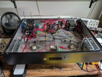
Status update: I'm well into the buildup of the amp chassis. I ordered the chassis from Landfall and they said it is the second biggest they have ever built.
In the back left corner, I have the +-15V supplies and the input boards. The input circuitry consists of balanced receivers, an opamp crossover that can be bypassed, and a balanced driver for a subwoofer output. I'm planning on having a bi-amped setup with a sub but if I ever change my mind all I have to do is flip a switch.
In the middle back, I have the plate supplies for the power tubes and the 6BN11. Each tube has its own pass device. I didn't want a lot of dissipation in any one device at these voltages. There is a decent heatsink on the back of the amp.
In the back right corner, I have the stacked 48V supplies for the +-144V rails for the mosfet grid drivers.
The filament/heater supplies live in the front corners. They are two stacked 5V supplies so I can accommodate pretty much any 5V to 10V transmitter tube filament. Each side is rated for 200W filament power, which is good because the 327A tubes have 110W filaments.
I'm working on the microcontroller/display in the front now. That part's probably more complicated than the tube audio circuit.
Attachments
Nice to see you're having at it. The wood table top is visible through the socket surround space on the fore left but not through the perf. Is there solid top plate under the rest?
Nice work. Re bunches of wires, have you tried cable lacing? It looks better than cable ties & is easy to do. There's a few video's on Youtube on how to do it all you need is some stout cord.
I'm curious as to how the chassis is constructed, any chance of a pic of the top?
Andy.
I'm curious as to how the chassis is constructed, any chance of a pic of the top?
Andy.
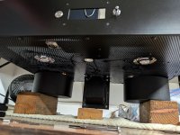
The top plate is perforated 1/8" aluminum.
I've never tried cable lacing, but I have seen plenty of old tube electronics that look beautiful inside with it. When I get to the tube signal circuitry I will probably not tie anything together as I would like to reduce capacitive coupling as much as possible with this high-feedback circuit.
I can't flip the amp yet, but here's a picture of the top with poor lighting and little space.
I had to make large holes for the power tubes since I would like to be able to sub in the other weird 100T variants I procured some day and 211s if desired, so that is the reasoning behind having a big hole in the chassis. I'm going to run 100THs first, which is the tube with the smallest base that I have. Luckily, fan grilles saved me from having to do much metal work to adapt the big hole to a smaller socket. The other tubes will have sockets that mount under the chassis and the base of the tube will be near the hole.
Attachments
@SpreadSpectrum what do you think about using the gyrator like in last @Tubelab_com thread ( https://www.diyaudio.com/community/threads/of-course-it-will-work-its-guaranteed.419415/ ) for the driver in your configuration with a pentode in UL for the output tube instead of a triode? I would like to try something different for the next amp, and it seems a simple solution joining two good ideas.
How negative must be the pmosfet drain? At least -25 for input capacitance stability?
How negative must be the pmosfet drain? At least -25 for input capacitance stability?
Last edited:
The main problem with a high-impedance load on a pentode is bias stability. Everything is balanced on a knife's edge.
I think the main advantage that the gyrator load would have over a CCS is that it might have more DC stability. I'd want to build one to be sure and do an A:B comparison to test distortion differences and bias stability differences.
I've solved the bias stability issue in this amp, but it might be nice to have something that doesn't require a computer like I'm doing here. I think a simple servo circuit that adjusts screen voltage to stabilize plate voltage is a pretty good solution as well.
- Home
- Amplifiers
- Tubes / Valves
- Corona: An Ultra-Low Distortion A2 DHT SE Amp Prototype