Have you looked at anything from Mill Max? I made some teflon sockets for 368A tubes a long time ago but never used them. Something from this series | Mill-Max Mfg. Corp.
Attachments
Have you looked at anything from Mill Max? I made some teflon sockets for 368A tubes a long time ago but never used them.
That looks really nice.
It seems like they make a socket that covers the size of the filament lead(.070"), but I don't see anybody who will just sell just half a dozen or so. Hmmm. I'll keep looking.
I imagine it'd do fine as long as the parts are up to the task, and that's kind of what I'm imagining. I picked out one of the new IXYS linear HV fets to start experimenting with, but it is backordered.
A cap multiplier is the best way to go and not that hard to implement at this level of HV given the availability of parts these days.
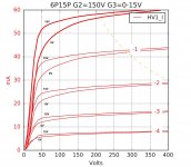
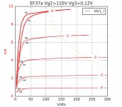
Interesting comparison between effect of G3 positive voltage in the EF 37a compared to a 6P15P. The latter would be better benefited from it. The EF37a has a less impact and in fact (as I measured) Vg3 higher than 12V has a negative effect. Whereas the 6P15V has a greater squaring of the curves (at higher Ia for sure). In the low Ia end for the EF37a, the low voltage current kink becomes more evident.
Attachments
I'm not too worried about the cap multiplier circuit, but it will be the first time I've gone to 750V with this much current draw.
Those are pretty cool curves. It's frustrating that some tubes internally tie G3 to cathode. It would be cool to see what could be done, say, to a 47.
Those are pretty cool curves. It's frustrating that some tubes internally tie G3 to cathode. It would be cool to see what could be done, say, to a 47.
Have you looked at anything from Mill Max?
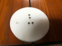
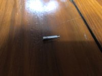
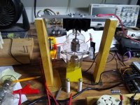
I just found a correctly-sized Mill Max socket in stock at Mouser that I added to my current order. It is a press fit into a certain hole size and has a solder cup. I think I'll try mounting it into a piece of FR4 and making a socket that way. It won't look quite as good as what you made, but I think it will work nicely.
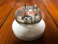
The Mill-Max sockets worked out well. Here's the structure I've put together for breadboard testing. I'll make the real thing look nicer.
Next step will be to draw some plate curves. That should be fun.
I also have some Electra-Print transformers on the way.
Next step will be to draw some plate curves. That should be fun.
I also have some Electra-Print transformers on the way.
Attachments
I'm sure the solution will be something simple: I'm trying to simulate the first stage only with an hybrid cascode and the CCS on the collector, but the only way to have gain is to increase the resistor bwtween the CCS and the cascode. What about the high impedance of the CCS? What am I doing wrong?
Thanks
Thanks
Attachments
The CCS practically not working.
Be sure, that -at least- 30V DC available on CCS (from input to output).
Be sure, that required current was setting in CCS: measured on setting resistor.
Be sure, that -at least- 30V DC available on CCS (from input to output).
Be sure, that required current was setting in CCS: measured on setting resistor.
BTW, with this R1 value, the CCS current is over 2mA, which is not too good for 12AX7.
0.8..1mA is enough, but it's not in DN2540 territory.
Maybe LND150 CCS is better.
0.8..1mA is enough, but it's not in DN2540 territory.
Maybe LND150 CCS is better.
I think the 826 Corona scheme would be perfect for Svetlana/Ryazan SV572-30 and could be easily adapted for cheaper SV572-160 and Shuguang 805A. All current production without topcap.
I wasn't aware of the Shuguang 805A. That would probably be the most cost-effective way to scale this up without any exposed voltages up top that I have seen. I was looking at Shuguang 211s as a possibility as well but the mu is a good bit lower than the 826.
Really, I think just about any output tube could be used as long as the input stage has the output swing capability to drive it to clipping, and the mosfet's rails are chosen appropriately. The input stage I'm using can easily swing 200V in either direction of the idle point right now.
When I first made the change from the 6384 to the 826, I just changed the mosfet supply rails around to accommodate the more positive grid drive and swapped the 826 in. It didn't matter that the output stage had 1/3 the gain, I got the same overall amp sensitivity and about the same power out, thanks to the feedback.
Best deal I found is $43 each for NEW Svetlana SV572-160 Power Triode Tube, tested | eBay. I really envy you guys in the states.
Last edited:
Hey SpreadSpectrum (and anyone else who would like to chime in) - while waiting for the mains transformer for my 801A design, I have been playing with simulations of your feedback topology. Previously I used plate the cathode feedback, but used a simple resistor on the cathode of the pentode gain stage, left unbypassed. Now I have been using your PMOS method with better results I think, and a gyrator load and DC feedback to the screen, nothing in the real world just yet.

Have a question for you though, something that was touched on before. As you might expect given the linearity of the EF37A, with increasing NFB, the THD output spectrum becomes 3rd harmonic dominant. In some of my prototypes, I did find this to have a negative effect on the sound. I had planned to use the minimum amount of NFB to achieve a 1:3 damping ratio for 8ohm speakers, and output impedance of roughly 2.67ohm, in hopes of maintaining a 2nd harmonic dominant distortion spectrum to mask higher-order odd harmonics.
I am starting to think that might not be achievable. Is the key to maintaining a 2nd harmonic dominant spectrum in these designs to use a somewhat low-linearity input pentode? My thought is this would increase asymmetrical distortions with a higher 2nd harmonic, in which case I might consider moving away from the EF37A 🙁
Last edited:
Transistor as 2SK170 symbol? 🙂
Use this.
Thank you 🙂 I will add to my library.
What are the load/operating conditions of the 801A?
Looking at 801A curves, I think it has great potential to be an odd-harmonic distortion generator with a good A2 operating point due to the symmetrical compression going toward cutoff and saturation.
The high-impedance triodes curves tend to expand right up until you hit saturation, so I'd expect 2nd harmonic to dominate right up to clipping, which is what my amp does.
Have you considered something like an 811A? You'd have a top cap to deal with, but it's a pretty option.
I honestly don't know what my input stage distortion profile looks like. Whenever I test it, it is so touchy with all that gain. I honestly haven't hooked it up to the distortion test rig. I've just focused on system-level measurements.
I see, thanks, 801A will be biased at a near 0Vg bias, ~320V / 60mA with a 5K OPT. Here is a load line.

I'm pretty committed to the 801A at this point, if it is an odd-harmonic distortion generator, I will need to optimize around that. Certainly isn't a deal-breaker, but I recall subjectively I was getting better results with a higher H2.
I'm pretty committed to the 801A at this point, if it is an odd-harmonic distortion generator, I will need to optimize around that. Certainly isn't a deal-breaker, but I recall subjectively I was getting better results with a higher H2.
- Home
- Amplifiers
- Tubes / Valves
- Corona: An Ultra-Low Distortion A2 DHT SE Amp Prototype