How do you think the sound of the 826 compares to a KT88?
In this circuit, with all the feedback, probably hardly any difference. KT88 will have less output power of course since it is a 40W tube.
Long term, I think I want to get some decent 40W SE output transformers and build a proper amp with this circuit. I want to build it so that it can be easily adapted to different high-impedance transmitting triodes (in ~50W or ~100W operating points). I'm thinking I'd design it so that I'd be able to flip it upside down and reconfigure in an hour or two for a different tube. I've got some thoughts on the power supply, which I'll probably document in this thread.
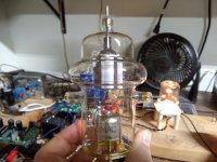
I have acquired a few 100THs, which look really cool. I have 6 good 826s now, which should last a while. I also have a couple of these 327-A tubes. One of them was given to me a long time ago and another I recently came across on Ebay for $25. I don't know if they are good tubes yet and I'd have to build a socket to hold them properly but they are basically a 100TH with a little lower mu and a 110W filament (designed for radar pulse duty in a ring oscillator). Hopefully neither has gone gassy over the years. Filaments are not open at least. Next Mouser order, I'll get a switching supply to light the filaments up and we'll see if we have any gas clouds.
I have acquired a few 100THs, which look really cool. I have 6 good 826s now, which should last a while. I also have a couple of these 327-A tubes. One of them was given to me a long time ago and another I recently came across on Ebay for $25. I don't know if they are good tubes yet and I'd have to build a socket to hold them properly but they are basically a 100TH with a little lower mu and a 110W filament (designed for radar pulse duty in a ring oscillator). Hopefully neither has gone gassy over the years. Filaments are not open at least. Next Mouser order, I'll get a switching supply to light the filaments up and we'll see if we have any gas clouds.
Attachments
Those 100TH are striking, will look great in an amplifier. Tried and failed to find curves for the 327-A, that is one oddball tube!
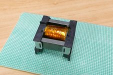
I received the Sowter transformers for my 801A amplifier. I typically work in my garage, but it is too cold to leave parts outside, got a foot of snow last week. Trying to come up with a practical way to throw together a single channel indoors, but soldering inside is frowned upon in my househould ha! It may have to wait until spring.

I received the Sowter transformers for my 801A amplifier. I typically work in my garage, but it is too cold to leave parts outside, got a foot of snow last week. Trying to come up with a practical way to throw together a single channel indoors, but soldering inside is frowned upon in my househould ha! It may have to wait until spring.
Yeah, the 327-A were specially made for radars so I don't think Eimac ever tried to market them to the public. I'll have to do a little curve tracing on my own. It is wild that they have a 110W filament and a 100W plate. Very inefficient but it should be quite the light show! They must have needed a lot of peak emission during the radar pulses.
Those transformers look nice. I'd like Sowter transformers for this project, but I think 40W iron from them would break the bank. I am strongly leaning toward Electra-Print at the moment.
I've been tiling the floors in the house so haven't had a lot of time to work on this but I've made it to the last room. Almost done!
Next I'll design the power supply. I want there to be a 750V B+ for 100W plate output tubes and a 550V B+ for the 826s. I want it to be a solid-state active ripple reduction circuit, but I don't want it regulated. I want it to drift up and down with line voltage so that the dissipation in the pass devices doesn't vary much with line voltage variation. I don't think I've seen anyone do it like that. I'll get a power transformer made with taps for the two output voltages.
Sowter transformer for 801a
Would you mind telling me the basic specs of these transformers? I believe you are using A2. I have several 801As and have believed for a while that A2 operation is a viable approach. Excuse me as I have not had time to fully explore the entire thread😱
Would you mind telling me the basic specs of these transformers? I believe you are using A2. I have several 801As and have believed for a while that A2 operation is a viable approach. Excuse me as I have not had time to fully explore the entire thread😱
Hope you will post those curves when you have them, very curious. 40W of iron from Sowter would cost a fortune I'm sure, I have been wanting to try Electra Print myself. FYI I reached out to Jack there recently and he is no longer offering custom mains transformers. Looking forward to seeing your final design, one step at at a time...
Hi! The transformers I showed are 5K:8ohm 60mA for a 0Vg A2 bias point, 320V 60mA on the 801A. Using transformers of this impedance necessitates NFB to reduce the output impedance to acceptable levels given the relatively high plate resistance of the 801A, I have seen others use a 3K primary for the 801A in A2 with more NFB. If you wanted to use them in a no NFB A2 design, a high primary impedance OPT will be necessary.
Would you mind telling me the basic specs of these transformers? I believe you are using A2. I have several 801As and have believed for a while that A2 operation is a viable approach. Excuse me as I have not had time to fully explore the entire thread😱
Hi! The transformers I showed are 5K:8ohm 60mA for a 0Vg A2 bias point, 320V 60mA on the 801A. Using transformers of this impedance necessitates NFB to reduce the output impedance to acceptable levels given the relatively high plate resistance of the 801A, I have seen others use a 3K primary for the 801A in A2 with more NFB. If you wanted to use them in a no NFB A2 design, a high primary impedance OPT will be necessary.
...Next I'll design the power supply. I want there to be a 750V B+ for 100W plate output tubes and a 550V B+ for the 826s. I want it to be a solid-state active ripple reduction circuit, but I don't want it regulated. I want it to drift up and down with line voltage so that the dissipation in the pass devices doesn't vary much with line voltage variation. I don't think I've seen anyone do it like that. I'll get a power transformer made with taps for the two output voltages.
In the past I have used multiple isolation transformers. I always scour the hamfests for budget isolation transformers or "industrial control transformers" that have two 120 volt primaries, and two 120 volt secondaries.
Feed the primaries from the line voltage, but hang a solid state FW bridge and a suitable large cap on each secondary to create a pair of independent isolated 150 to 175 volt DC sources. Using several transformers one can make several such DC supplies that can be interconnected in series or parallel for higher voltages and currents as was commonly done in Tektronix scopes during the vacuum tube era.
Most isolation transformers are not exactly 1:1. The secondary usually has a few more turns to make up for transformer losses at full load. This allows for using the transformer backwards to reduce the output voltage a bit.
It is also a good idea to place a hefty diode directly across the output so that the output cap will not be reverse biased if one individual supply shuts down for some reason.....I always fuse each individual supply so that things like a blown diode or cap doesn't create a fireball.
I have wired as many as 6 individual supplies made from 3 hamfest toroids in series fed from one Variac to make a zero to 950 volt supply.
I have been using a similar supply made from two 600 VA dual secondary medical grade toroids for testing in a big amplifier design. I want to build a vacuum tube kilowatt (500WPC) amp, but size and weight are the limiting factors. The supply has 4 outputs, one from each individual supply, for 160, 320, 480 and 640 volts at about 1/4 amp. The supply drops too much under load to support 500 WPC. I would need bigger transformers, or a third transformer with a single secondary, which I have.
The combined weight of the two large power toroids, the single secondary toroid, and the two Plitron toroidal OPT's and the SMPS for tube heaters alone (no chassis, tubes, capacitors or amp circuitry) is over 75 pounds, so I have been exploring DIY SMPS designs using the same stacked supply approach. So far I have made plenty of dead silicon and one transformer core that unexpectedly shattered. Further experiments are on hold due to lab renovations.
It looks like in addition to the 400VAC transformer I am using, I could make everything work if I added a 120VAC winding and a couple of smaller 24V windings. I could probably find some reasonably-priced transformers that fit the bill.
I'm thinking for the ripple-rejection circuit, first cut would be a LC filtered voltage to hang a mosfet gate on and take the ouput from the source. I'll see if that gets output ripple down low enough to make it inaudible or if it needs further refinement. I might give one of those IXYS linear HV fets a try here.
I too have considered stacking switching supplies but I can't find anything that looks like it would work in my price range over 48V and that's a lot of supplies to stack at 48V.
That was the issue I ran into. The highest voltage available in a low priced SMPS is 48 volts, and I need about 650 volts at nearly 3 amps.
My first experiments tried to make a lower power 650 volt SMPS. Those all ended in fried parts. I think there were just too many turns on the transformer secondary. It got hot even with no load.
I'm now thinking six or so stacked 110 volt 1.5 amp supplies per channel, or maybe 6 total at 3 amps each. That will give me 220 volts for the screen supply and 110 volts for the positive bias source. I would probably switch of the higher voltage supplies when I don't need a full kilowatt of power🙂
I bought all the parts and wound the transformer for one but that's as far as I got.
Attachments
That is up to you 😀
but the greenish bits of glass contain a few % of uranium which makes it glow under UV light.

but the greenish bits of glass contain a few % of uranium which makes it glow under UV light.
I have started falling down a Eimac transmitting triode rabbit hole...
The 3C24 / 24G has caught my eye as an interesting triode to try in the types of feedback topologies being discussed here.
http://r-type.org/pdfs/hk24.pdf
SpreadSpectrum - I've noticed with many of the Eimac transmitting triodes, they use wire leads to the grid and anode, requiring finned heat-dissipating caps, Eimac's HR series from what I have gathered, like below.
Silly question, but is it understood that when using these tubes in an audio amplifier the plate voltage will be exposed on these caps? Trying to imagine a future where I can experiment with a 3C24 design and feel comfortable leaving 300V outside of the chassis...not sure that future exists!
Ah I see, I figured a cage of some sort would be appropriate, but I like the glass! Wouldn't want to obscure these beautiful tubes. Thanks for the ideas, gents.
I was planning on building a cage (that is easy to see through). I didn't see any way to make a heat-dissipating cap that was electrically insulated and I too don't like the idea of exposed HV.
My recent tube acquisitions require all different sizes of caps and even a custom socket design. I've been buying aluminum rod and some LED heatsinks. I'm going to drill and tap holes as appropriate to make something similar to the old Eimac plate/grid caps. I've got the old Eimac caps for the 100TH, but this other tube has leads coming out everywhere and had a complex structure holding it in it's original application (radar).
I just bought an LED heatsink to try making a plate cap. I didn't look carefully at the drawing and it is much bigger than I expected. The heatsink is about the same diameter as the tube.
I'm with you on the cage / clear case with ventilation SS, definitely not okay with the HV exposed. Interested to see how your Eimac caps turn out, I was able to hunt down some HR2 sized caps, should work for the 3C24. No idea what will come of this but fun to mess around with these transmitting tubes. I found a cheap pair of HK54 as well, 3C24s big brother.
I have been thinking over some ideas on my 801A A2 amplifier. I was using a source follower FET before with plans to get a 0V bias point using a DC regulated heater supply for the EF37A, making the gate of the source follower FET a few volts positive by taking a tap from the regulated heater supply. I tried this out with a filament supply I had laying around maybe two months ago with mixed results. I'm sure I could improve upon it, but I'm not loving the idea.
I am considering dropping the source follower and going with a 6BX7 cathode follower with a current sink instead, like below. Adjustable LND150 CCS sets the grid voltage on the 6BX7 so the cathode can be adjusted easily to both sides of 0V to dial in a perfect 60mA bias on the 801A. I like it!

Other thing I would like to experiment with is using a VR105 voltage regulator tube to get 105VDC on the EF37A screens. Won't be as robust as the feedback mechanism in the schematic above, but drift has not been an issue for me so far even without it, which I attribute to leaving the EF37A cathodes unbypassed - open loop gain is not as crazy high as some of the other CCS loaded pentode stages in this thread. We'll see how it goes!
I have been thinking over some ideas on my 801A A2 amplifier. I was using a source follower FET before with plans to get a 0V bias point using a DC regulated heater supply for the EF37A, making the gate of the source follower FET a few volts positive by taking a tap from the regulated heater supply. I tried this out with a filament supply I had laying around maybe two months ago with mixed results. I'm sure I could improve upon it, but I'm not loving the idea.
I am considering dropping the source follower and going with a 6BX7 cathode follower with a current sink instead, like below. Adjustable LND150 CCS sets the grid voltage on the 6BX7 so the cathode can be adjusted easily to both sides of 0V to dial in a perfect 60mA bias on the 801A. I like it!
Other thing I would like to experiment with is using a VR105 voltage regulator tube to get 105VDC on the EF37A screens. Won't be as robust as the feedback mechanism in the schematic above, but drift has not been an issue for me so far even without it, which I attribute to leaving the EF37A cathodes unbypassed - open loop gain is not as crazy high as some of the other CCS loaded pentode stages in this thread. We'll see how it goes!
Last edited:
...
Other thing I would like to experiment with is using a VR105 voltage regulator tube to get 105VDC on the EF37A screens. Won't be as robust as the feedback mechanism in the schematic above, but drift has not been an issue for me so far even without it, which I attribute to leaving the EF37A cathodes unbypassed - open loop gain is not as crazy high as some of the other CCS loaded pentode stages in this thread. We'll see how it goes!
Recently I've been playing a while with the EF37a. A beloved pentode which I used extensively in the past. The results are here:
Mono Amp: EF37a driver (part II) – Bartola(R) Valves
As discussed with JC Morrison, setting the screen voltage to the right sweet spot is key to minimise distortion of the driver stage. I found it around 115V for an anode voltage of 235V. The DC feedback is key to avoid drift in my opinion.
Ale
- Home
- Amplifiers
- Tubes / Valves
- Corona: An Ultra-Low Distortion A2 DHT SE Amp Prototype