Dear SpreadSpectrum,
while thinking on how to apply your system to cascode, another idea came to my mind.
You use an (almost) horizontal loadline with a pentode, while Rod Coleman uses a vertical loadline with a triode ( Shunt Cascode Power Valve Driver ). Your feedback back to the cathode of the triode can be applied too.
I will try to simulate it.
I will simulate a PP version too, with a power MOSFET concertina phase inverter and ouutput tubes in pentode/UL can have anode to grid shunt feedback with a voltage divider to a negative voltage supply to give at the same time a bias reference to the grid (your feedback cannot be applied in that case, or at least I cannot see how).
Last edited:
It would not be a "Shunt", AKA Parallel feedback, it would be a series feedback.
6V6 P-P Amp From RCA Manual RC-19
6V6 P-P Amp From RCA Manual RC-19
Thank you Wavebourn, I've seen your post here: 6V6 P-P Amp From RCA Manual RC-19
and here: Schade Feedback
and here: Schade Feedback
Magz did summat similar elevating the cathode with his 833 midlife crisis amp
Have a read of that thread
The Midlife Crisis - My 833C Amp Build
stay safe
t
Have a read of that thread
The Midlife Crisis - My 833C Amp Build
stay safe
t
timgrindell, if the schematic is the one on page 1, that one is a "common" horizontal loadline on a triode, driving a triode. So nor the innovative circuits by SpreadSpectrum nor the one by Rod Coleman. Is the circuit changed somewhere in the other 89 pages of that thread?
zintolo,
i don't need to be challenged by you especially when you haven't bothered to read that thread.
My reply was directed to L0rdGwyn hence the "elevating the cathode" comment.
t
i don't need to be challenged by you especially when you haven't bothered to read that thread.
My reply was directed to L0rdGwyn hence the "elevating the cathode" comment.
t
timgrindell,
I don't really care about challenging anyone. I'm here to learn.
So boil down yourself please. No need to bring tension in a forum.
Just to remember the rules of the netiquette, when you refer to a post that is not the last one, you need to specify it. And when you link something, you need to be specific, as linking a 89 pages thread is not proper. It's not me saying that, it's the netiquette.
Peace.
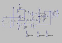
I made some tests with SpreadSpectrum's FB topology on the E130L SET I showed in post #94 Corona: An Ultra-Low Distortion A2 DHT SE Amp Prototype.
Here is my test setup:

The CCS I used on EF37A was similar to Gary Pimm's Self-bias CCS. I tested GFB with mosfet (1) and without (2). The measurements were made at roughly 1W using 6.8 ohm resistor as load. I made measurements at output and after EF37A (A on the schematic).
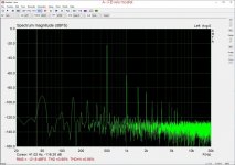
The results were quite disappointing (see attachments):
GFB with Mosfet
THD @Output: 1.56%
THD @A: 0.40%
GFB w/o Mosfet
THD @Output: 1.35%
THD @A: 0.95%
Without GFB
THD @Output: 0.068%
THD @A: 1.50%
I think the low THD without GFB is due to significant distortion cancellation between stages and output transformer. Applying FB lowers the distortion after driver but the distortion cancellation does not work as well resulting in higher distortion at output.
Another drawback of this setup was that CCS on EF37A made it very prone to oscillations. EF37A is probably too wimpy for CCS.
Here is my test setup:
The CCS I used on EF37A was similar to Gary Pimm's Self-bias CCS. I tested GFB with mosfet (1) and without (2). The measurements were made at roughly 1W using 6.8 ohm resistor as load. I made measurements at output and after EF37A (A on the schematic).
The results were quite disappointing (see attachments):
GFB with Mosfet
THD @Output: 1.56%
THD @A: 0.40%
GFB w/o Mosfet
THD @Output: 1.35%
THD @A: 0.95%
Without GFB
THD @Output: 0.068%
THD @A: 1.50%
I think the low THD without GFB is due to significant distortion cancellation between stages and output transformer. Applying FB lowers the distortion after driver but the distortion cancellation does not work as well resulting in higher distortion at output.
Another drawback of this setup was that CCS on EF37A made it very prone to oscillations. EF37A is probably too wimpy for CCS.
Attachments


I'm not sure how negative feedback could make distortion worse like that. The only thing outside the loop that could cancel distortion would be the transformer, but I don't see it producing that much.
Have you measured distortion at the output tube plate? Something seems off here.
Have you measured distortion at the output tube plate? Something seems off here.
... I may have to ask Rod's opinion on using his filament regulators on top of an elevated supply ...
It works without any notable problems. The Raw DC must of course be fully floating, and not shared with any other load. The whole just floats on top of the 200V supply.
Precautions:
We just need to be sure that any shorts from Raw DC to chassis/Ground are not easy accidents! Mount the Raw DC recifiers/caps on tall mounting pillars (preferably Nylon, etc), and the same with the filament regulators - they make a good distance from Raw DC components to chassis.
The heatsink interface for the power transistors should be made carefully. The mica insulators are no problem - but using clips in place of screws to mount the transistors avoids risks around the TO-220 holes. Example clips: Aavid MAX07NG; Laird TSC607-ZP.
When using a 200V regulated supply in the cathode circuit, don't forget to check the phase response, if it becomes part of any feedback loop. Many IC regulators rotate phase inductively, which is not helpful !
I'm not sure how negative feedback could make distortion worse like that. The only thing outside the loop that could cancel distortion would be the transformer, but I don't see it producing that much.
Have you measured distortion at the output tube plate? Something seems off here.
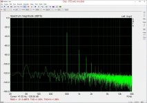
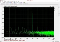
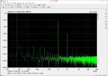
Here are measurements from A (after EF37A), E130L plate and after output transformer using mosfet GFB and without GFB. I lowered the FB resistor to 110kOhm so the distortion with mosfet GFB is now a tad lower. As can be seen the output transformer does not have much effect on the THD. The distortion cancellation occurs mainly between driver and output tubes. In the mosfet GFB version the mains related spuries are lower. This may also be related to having CCS anode load on EF37A.
Strictly speaking these are not the same circuits as the GFB version uses CCS as EF37A anode load where the non-GFB version has resistor anode load and led bias on EF37A. This may explain the rather unexpected outcome of applying GFB.
Attachments


It works without any notable problems. The Raw DC must of course be fully floating, and not shared with any other load. The whole just floats on top of the 200V supply.
Thanks for the input, Rod, I'll keep your points in mind. I am going to attempt a prototype, need to work out some quirks, particularly the best way to bring the 801A up to bias with the direct-coupling and elevated filament supply in place.
And timgrindell - thanks for the link, I will search that thread for info on the filament elevation.
I appreciate the help, I'm eager to learn but without any EE education, so getting advice here on the forum is invaluable to me.
Strictly speaking these are not the same circuits as the GFB version uses CCS as EF37A anode load where the non-GFB version has resistor anode load and led bias on EF37A. This may explain the rather unexpected outcome of applying GFB.
Ok, that makes sense. You probably did just get really lucky and found a good combination of input/output tube that cancels distortion.
As for the feedback circuit performing at such poor levels, I'll have to look your circuit over some more when I have time. Typically, I see more distorted levels inside the loop (since the feedback works to drive levels to where they need to be to cancel the distortion). My output tube grid waveform at 19W output looks like a triangle wave, but distortion at the plate is only 0.3%. I'm sure THD at the grid is off the charts under those conditions.
You probably did just get really lucky and found a good combination of input/output tube that cancels distortion.
Actually this all started way back in 2005 when I traced real triode curves of some E130Ls I had. I noticed that some of them had very low distortion (actually much lower than the Spice models predict) so it is not pure luck 😀.
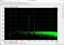
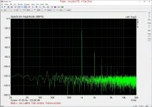
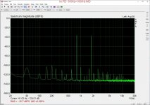
And for those of you having some doubts about the distortion cancellation here are some two-tone IMD measurements without GFB. At 800Hz+1800Hz, 11kHz+12kHz and DIN IMD (250Hz+8kHz).
Attachments

As for the feedback circuit performing at such poor levels, I'll have to look your circuit over some more when I have time. Typically, I see more distorted levels inside the loop (since the feedback works to drive levels to where they need to be to cancel the distortion). My output tube grid waveform at 19W output looks like a triangle wave, but distortion at the plate is only 0.3%. I'm sure THD at the grid is off the charts under those conditions.
Actually the FB circuit can be "tuned" in the same fashion as the non-FB circuit by adjusting the screen resistor of EF37A. Tuned to the the minimum THD setting for non-FB, the THD for FB circuit was more like you described: higher distortion at output tube grid but with this setting the output THD was more than 1%. The measurements I showed earlier were made after tuning the FB circuit to minimum THD which also had a lower THD at output tube grid. But like I said before the CCS anode load on EF37A made the whole circuit very touchy. It burst into oscillations very easily so tuning for minimum THD was difficult.
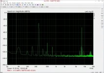
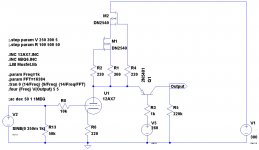
Following the idea of applying cheap triodes with vertical loadlines instead of pentodes with horizontal loadlines, I've optimized the gain of a simple half of 12ax7 to obtain a gain of 355 and 250Vpp with 1,21% THD:
I would like to implement a gyrator to directly apply the bias voltage (all stages can be DC coupled, as suggested here: The Shunt Cascode Driver – Bartola(R) Valves ) and shunt feedback anode to grid through a simple resistor as suggested by Rod.
Then I'll apply the feedback as suggested by SpreadSpectrum.
It seems to me a good choice for driving-demanding PP as well, before a concertina.
Code:
Harmonic	Frequency	 Fourier 	Normalized	 Phase  	Normalized
 Number 	  [Hz]   	Component	 Component	[degree]	Phase [deg]
    1   	1.000e+03	1.240e+02	1.000e+00	  179.88°	    0.00°
    2   	2.000e+03	1.498e+00	1.208e-02	   92.40°	  -87.48°
    3   	3.000e+03	1.362e-01	1.099e-03	 -163.85°	 -343.73°
    4   	4.000e+03	1.335e-02	1.076e-04	  -10.39°	 -190.27°
    5   	5.000e+03	1.632e-02	1.316e-04	   74.18°	 -105.70°
    6   	6.000e+03	7.311e-03	5.895e-05	  -89.50°	 -269.38°
    7   	7.000e+03	2.077e-02	1.675e-04	 -156.55°	 -336.43°
    8   	8.000e+03	1.636e-02	1.319e-04	  111.09°	  -68.79°
    9   	9.000e+03	1.453e-02	1.172e-04	 -119.22°	 -299.10°
Total Harmonic Distortion: 1.213595%(1.214360%)
I would like to implement a gyrator to directly apply the bias voltage (all stages can be DC coupled, as suggested here: The Shunt Cascode Driver – Bartola(R) Valves ) and shunt feedback anode to grid through a simple resistor as suggested by Rod.
Then I'll apply the feedback as suggested by SpreadSpectrum.
It seems to me a good choice for driving-demanding PP as well, before a concertina.
Attachments
I have not said anything about shunt Cascode for a while - but I have been working on it!
Expect the distortion to be a lot lower, with many optimisations for the new design. More to say, when I get the boards back, and I have the measurements.
FET concertina should work well for PP - I will think more about it and reply to your question about that!
Expect the distortion to be a lot lower, with many optimisations for the new design. More to say, when I get the boards back, and I have the measurements.
FET concertina should work well for PP - I will think more about it and reply to your question about that!
Thanks Rod,
in the meanwhile I've read this thread about Mosfet "source-o-dyne" ( Mosfet or other semiconductor substitute for cathodyne? ). On the PP side I would like to drive the output stage of the "Final amp" (EL34 Baby Huey Amplifier ) with shunt feedback as well, driven by this configuration. Or a pair of KT88 like in this other amp made by SpreadSpectrum ( Amp: KT88 push-pull shunt feedback output via p-channel fet ).
As for the SE amp tests, can you suggest me a big octal-based output-tube that can benefit from this kind of wide drive and costs less than 40/50€ each?
Thanks
I've been working slowly on this for a while. Here are updates from the past month:
1. I got the bias servo working on the first stage. It was very stable on the first stage alone, but once I put the output tube back in I got some LF oscillations. I decreased the coupling cap between stages by half (2Hz cutoff went to 4Hz cutoff) and lowered the gain of the servo. It has a bit of LF overshoot visible but seems pretty stable. I still have about 6dB of gain I can give up so I might try that next.
2. I changed the plate load of the input stage when I installed the servo. Instead of 1M in parallel to the CCS, there is 1M to GND, which is actually the voltage sense for the servo as well. The 1M is actually 2 2M resistances in parallel, one for the servo voltage sense divider and the other for just added resistance. I did try running the input stage with 2M load and I got a gain of ~4300, which is almost double the gain of ~2300 that I measured with the 1M plate load. There is still more gain available should I ever desire to go after it. The amp is good enough as-is but it might be cool to see if I can hit .01% at 1W.
- Home
- Amplifiers
- Tubes / Valves
- Corona: An Ultra-Low Distortion A2 DHT SE Amp Prototype