You could include the OPT in the GBF. You could even take some of the FB from the secondary and the HF from the primary.
If you have a good output transformer, that could work just fine. I'm imagining something like Patrick Turner's 13E1 SE.
This approach was meant to showcase what is possible with inexpensive output transformers that may not behave well enough to use a global loop.
This approach was meant to showcase what is possible with inexpensive output transformers that may not behave well enough to use a global loop.
Well, for me looks are a significant factor so I like the glowing heater wire on the top that goes between the two cathodes and the open plate structure so you can see the grids and the cathodes. The high-ish gain allows me to really design whatever gain I want with my choice of load. Right now, the Corona bench design has like 35dB of feedback (IIRC) with the 1M||CCS plate load on the 6BN11.
I also kind of like the idea of taking compactron tubes which were the very last generation of tubes and pairing them up with some of the oldest tube designs that I can get my hands on for a reasonable price. I'm sure nobody ever did that in the tube days, and I like doing things in ways that haven't been done.
It's a cool concept, mating the old with the new, I'd imagine a tube like the 6BN11 would blow the mind of a early 1940s engineer. I wonder if there has ever been a lower distortion single-ended class A amplifier before Corona.
I was able to track down two more pairs of HK54, so I now have three pairs. I've come up with a few different variations of the design and I've decided I'm going to build it, not sure when, but will need to be breadboarded of course. Will shoot for the stars and go for 15W.
Patrick Turner's 13E1 SE does better, but that's the only one I've been able to find. It uses a cathode feedback output transformer he made himself and a global feedback loop.
Still, what you've accomplished with off-the-shelf parts and local feedback is very impressive.
Yeah, it was definitely better results than I had hoped for, especially using just vanilla Edcor transformers.
Three pair of HK54 is probably enough to keep an amp going for a long time. I've been acquiring tubes and have got 7 100THs, 3 327As, 5 VT127As, and 8 826s.
I was going to just make one SE amp but I may have to make more or these tubes will never get used. I've already got two pairs of output transformers. 😀
I'm hoping to find more, we will see, they might pop up from time to time. Nice collection, should make for a nice fleet of SE amplifiers 🙂 someone on this forum once told me that once you start with transmitting triodes, you never go back, that is proving to be true for me...
It's been a bit addicting. I'll admit I was pretty damn excited when the 5 VT127As that I bought without any warranty for $19 each all turned out to all be good tubes.
They are lower mu than any of the other types, so I may build an amp specifically for those. I also want to get some Chinese 211s and experiment with them since they are very similar mu to the VT127As (which themselves are just a repackaged 100TL with a beefier filament).
I think next on this project, I'm going to try to just fit a 100TH into the circuit in place of the 826 at a similar operating point. Then I'll start building a new power supply. I've been using Tom Christiansen's Maida regulator, but I think I want something that just rejects ripple and doesn't regulate voltage. Planning for high line voltages gets complicated when designing a 700V supply for this amp. I don't want to have a gigantic heatsink if that isn't necessary. I'll make the bias servo turn output tube current down if line voltage creeps up too high.
But right now I'm repairing a crackling channel in my Unity Coupled amp, so this will all have to wait a bit.
The VT127A are very eyecatching. Another interesting tube is the 4E27A, they have very linear triode-strapped A1 curves.
I hear you on the Maida regulator, I use a friend's Maida design, similar to Tom's but it uses a different LDO regulator. It's great, I've used it in my phono stage, 841 amplifier, and now in the 801A design. Tricky once you start pushing high voltage / current, I've sinked it to the chassis thus far but probably not practical with the HK54. If you have excess voltage, helps a bit to use a larger reservoir cap to cut down on ripple and some series resistance before the regulator to minimize voltage drop across the FET, kind of a balancing act running the reg closer to dropout to cut down on heat, but I'm sure I'm preaching to the choir 😀
Good luck with the fix. I am thinking I might sell those LL9202 after all ha! Need to finance some iron for this HK54 build.
I was thinking about a simple way to square up the curves of the EF37A in my 801A prototype. Ale seemed to find that 12V on g3 gave the best harmonic result. I wonder if I could just stick a 12V A23 battery in between g3 and the cathode.
I tried the above with a 9V battery as a proof of concept. I measured it beforehand at 9.5 volts.
Here are the curves, red at 0Vg3, blue at 9.5Vg3.
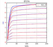
Most pronounced improvement at low grid voltages, will be interesting to see how it affects THD in circuit. I measured the g3 current as well while taking a measurement, roughly 5µA.
A 9V battery has a 500mAh rating, so at 5µA draw, that's 100K hours. Meanwhile a 12V A23 has a 55mAh rating, and current draw will be higher, guesstimation 8µA, so roughly 7K hours.
Here are the curves, red at 0Vg3, blue at 9.5Vg3.

Most pronounced improvement at low grid voltages, will be interesting to see how it affects THD in circuit. I measured the g3 current as well while taking a measurement, roughly 5µA.
A 9V battery has a 500mAh rating, so at 5µA draw, that's 100K hours. Meanwhile a 12V A23 has a 55mAh rating, and current draw will be higher, guesstimation 8µA, so roughly 7K hours.
You can kind of see that it causes some little kinks at very low currents, though, so you would want to be mindful if you ever wanted to operate there.
You could install some tip jacks in the amplifier top panel that could allow you to easily measure the battery voltage if you ever wondered if they needed to be replaced.
You could install some tip jacks in the amplifier top panel that could allow you to easily measure the battery voltage if you ever wondered if they needed to be replaced.
Yeah, looks like the tetrode kink is back for revenge. Given my load and operating point, I likely won't swing near the kink, or even near the improved knees, so I wonder if there will be any real world benefit. Only one way to find out, will try it out on the bench.
I tried the above with a 9V battery as a proof of concept. I measured it beforehand at 9.5 volts.
Here are the curves, red at 0Vg3, blue at 9.5Vg3.
View attachment 937030
Most pronounced improvement at low grid voltages, will be interesting to see how it affects THD in circuit. I measured the g3 current as well while taking a measurement, roughly 5µA.
A 9V battery has a 500mAh rating, so at 5µA draw, that's 100K hours. Meanwhile a 12V A23 has a 55mAh rating, and current draw will be higher, guesstimation 8µA, so roughly 7K hours.
I wonder if your tube tester would be capable of testing Jfets. I would love to see how something like a J310 compares to a pentode/tetrode in a direct comparison.
I'll keep it in mind next time I am messing around with JFETs.
I grabbed some 6EW6 SpreadSpectrum, a five pack of Amperex-made. Interesting little tubes, didn't expect them to be so small.
I know they were not made for precision, but it's a good thing they are cheap and plentiful, the curves are all over the place . I was able to make one reasonably matched pair from the five. I wonder if the tolerances are better with different brands, I have a trio of RCA-made on the way as well, I guess we will see.
Interesting. I've just worked with 1 6EW6 and 1 6BN11 so far, but I've purchased dozens of the 6BN11.
I've got various marked brands, but it looks like only 2 actual manufacturers, GE and Sylvania, I believe.
I'm not all that concerned with the required grid bias on each particular tube since the bias servo will take care of that, but I'd be concerned if transconductance at a particular operating point varies wildly from sample to sample.
Unfortunately the differences can be large. If the tube labels are to be believed, these are Holland-made Amperex, typically high quality.
Here is some data. I measured gm for each tube at a 200Va, -1.3Vg1, 115Vg2. Difference in gm was 40% at worst, 7% at best. Wish I could say that 40% was an outlier, here are the measurements for each.
And the curves at 115Vg2.
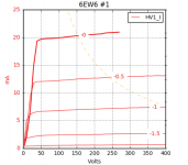
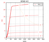
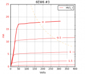
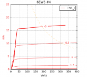
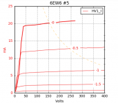
Can't say if the same variance would be seen in a 6BN11 lineup, I would hope the sections would be somewhat well-matched at least.
Here is some data. I measured gm for each tube at a 200Va, -1.3Vg1, 115Vg2. Difference in gm was 40% at worst, 7% at best. Wish I could say that 40% was an outlier, here are the measurements for each.
- 8610mhos
- 9222mhos
- 6391mhos
- 5461mhos
- 7063mhos
And the curves at 115Vg2.


Can't say if the same variance would be seen in a 6BN11 lineup, I would hope the sections would be somewhat well-matched at least.
Last edited:
Definitely quite a bit of variation there, but I'm wondering if you adjust the bias so that they are all at the same quiescent plate voltage/current, do the transconductances match better? Can you get them to match well by adjusting screen voltage?
If so, then it wouldn't be much of a problem in an amp that adjusts the bias through grid bias or screen bias servo.
From the graphs, it looks like the answer might possibly be yes.
If so, then it wouldn't be much of a problem in an amp that adjusts the bias through grid bias or screen bias servo.
From the graphs, it looks like the answer might possibly be yes.
I gave screen adjustment a try with the most extreme example, tubes 2 and 4. I dialed down the screen voltage for tube 2 until the curves were a well-matched, then remeasured the transconductance at 200Va / -1.3Vg1. This put Vg2 on tube 2 at 83V vs. 115V on tube 4. Transconductance with the screen adjustment was 5111, compared to 5461 on tube 4.
Here the curves overlaid.
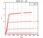
That's the most extreme example, so seems like a variable regulated screen supply would account for sample variation.
Here the curves overlaid.

That's the most extreme example, so seems like a variable regulated screen supply would account for sample variation.
- Home
- Amplifiers
- Tubes / Valves
- Corona: An Ultra-Low Distortion A2 DHT SE Amp Prototype