Thank you for suggesting it, glad to have a simple fix. I bought a pack of 6AH6 to try as well, hoping to take a KISS approach and use a resistive load on the pentode stage of a HK54 design. I have six here and two more on the way, that oughta do it.

Me too, that is the odd one out in terms of construction, an older vintage I think. Hoping one of the final two will match it, the filament is very impressive with the open plate.
211 as a driver for A2
Just came across this thread, I built a class A2 805, based on shishido san's operating points for class A2. I used a mosfet source follower - concept that I picked up mosfet follies website, coupled with Tubes Labs, Ale's work around SF's
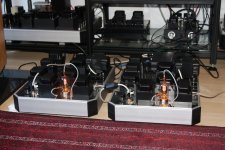
I have a 2 stage setup - 211 choke loaded with coupling cap into a source follower driving the grid of 805. The B+ is 900V for both the tubes, and 211 is biased at -40V/40mA, so I think, it can pretty much take what you throw at it.
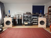
I don't have the tools or the expertise to measure like ale or rod or others in the group, but this is by far the best amp I have built. The plate chokes and output 3K xformers are from monolith magnetics and I have a 16 ohm local feedback from the output transformers.
I have used dht linestages for the longest time, the last one being a a 801A linestage with filament biasing using gyrator output, dueland caps, and Rod's filament supply.
A month ago, I decided to explore SS linestage from benchmark audio - LA4 preamp, I have to admit and I will preface this with a strong caveat, this 'my opinion' based on my system, my choice of music and my preferences -- the 801A was close to the benchmark, something like 90%, the extra 10% was the difference in detail coming thru in the benchmark. I would be the first to admit, I am sure if Ale tweaked with it, it go to a different level, but then, at old age, just having a component that sounds as good with a the luxury of remote nails it.
The amp was a different story, I found the intimacy in my 50W 805 A2 amp was a little more than the benchmark AHB2 amp, so I finally decided with benchmark pre and my own amp. btw, the feeling could be because of the euphonic nature of my amp 🙂. I live the San Francisco bay area, and if somebody local has the equipment to measure, more than happy to bring it over for measuring, I will also learn.
The entire chain was - volumio primo streamer --> rme dac2 --> bencmark LA4 --> 211--805 amp --> Zu Audio Defs.
I was blasting thru qobuz hi-res music few nights ago, system held firm, no apparent sign of distortion, with the soundstage holding well with apparent good clear separation of instruments..
I do feel the 211 driver is making all the difference, just having that head room with the high gain setup makes it easy to build 2 stage amps.
btw, my previous amp was 811A class A2 using 6E5P driver with a source follower driving 811A
I have parts in my garage for a 211--211 amp with a 15K output transformer from monolith magnetics. Will get to it sometime this year..
cheers
Sridhar
Just came across this thread, I built a class A2 805, based on shishido san's operating points for class A2. I used a mosfet source follower - concept that I picked up mosfet follies website, coupled with Tubes Labs, Ale's work around SF's
I have a 2 stage setup - 211 choke loaded with coupling cap into a source follower driving the grid of 805. The B+ is 900V for both the tubes, and 211 is biased at -40V/40mA, so I think, it can pretty much take what you throw at it.
I don't have the tools or the expertise to measure like ale or rod or others in the group, but this is by far the best amp I have built. The plate chokes and output 3K xformers are from monolith magnetics and I have a 16 ohm local feedback from the output transformers.
I have used dht linestages for the longest time, the last one being a a 801A linestage with filament biasing using gyrator output, dueland caps, and Rod's filament supply.
A month ago, I decided to explore SS linestage from benchmark audio - LA4 preamp, I have to admit and I will preface this with a strong caveat, this 'my opinion' based on my system, my choice of music and my preferences -- the 801A was close to the benchmark, something like 90%, the extra 10% was the difference in detail coming thru in the benchmark. I would be the first to admit, I am sure if Ale tweaked with it, it go to a different level, but then, at old age, just having a component that sounds as good with a the luxury of remote nails it.
The amp was a different story, I found the intimacy in my 50W 805 A2 amp was a little more than the benchmark AHB2 amp, so I finally decided with benchmark pre and my own amp. btw, the feeling could be because of the euphonic nature of my amp 🙂. I live the San Francisco bay area, and if somebody local has the equipment to measure, more than happy to bring it over for measuring, I will also learn.
The entire chain was - volumio primo streamer --> rme dac2 --> bencmark LA4 --> 211--805 amp --> Zu Audio Defs.
I was blasting thru qobuz hi-res music few nights ago, system held firm, no apparent sign of distortion, with the soundstage holding well with apparent good clear separation of instruments..
I do feel the 211 driver is making all the difference, just having that head room with the high gain setup makes it easy to build 2 stage amps.
btw, my previous amp was 811A class A2 using 6E5P driver with a source follower driving 811A
I have parts in my garage for a 211--211 amp with a 15K output transformer from monolith magnetics. Will get to it sometime this year..
cheers
Sridhar
Hi Spreadspectrum,
I'm interested in what cut-off frequencies you used for the input stage high pass filter and the coupling to the output stage. With such a high gain is there any danger of overloading the input stage with a low level subsonic signal when there is reduced feedback due to roll-off from the coupling capacitor? I ask because I'm planning somrthing similar and the simulation says there might be problems unless I have quite a high cut-off frequency at the input. Probaby not a real-life problem.
I'm interested in what cut-off frequencies you used for the input stage high pass filter and the coupling to the output stage. With such a high gain is there any danger of overloading the input stage with a low level subsonic signal when there is reduced feedback due to roll-off from the coupling capacitor? I ask because I'm planning somrthing similar and the simulation says there might be problems unless I have quite a high cut-off frequency at the input. Probaby not a real-life problem.
tikiroo,
The input is a 127k bias resistor and 0.2uF coupling cap, so a cutoff frequency of 6.3Hz. The interface between the input stage plate and the source follower is a 3.3M bias resistor and .022uF coupling cap, so a cutoff frequency of 2.2Hz.
I've got a bias servo that sets bias on the input stage and I don't see the plate voltage wandering due to LF noise coupling in from the input on the bench. The bias servo would work against that, if it is in a frequency range that it has some gain.
The servo does have a bit of overshoot when setting the bias. I tried a .57uF coupling cap on the input and there was significantly more overshoot. I'm in the process of optimizing the servo behavior but the high gain of the input stage makes this more of a challenge than any other stage I've used a bias servo on.
sganti,
If the 211 datasheet curves are true, then it has to be one of the most linear tubes out there. I'm going to eventually pick some up and try them in this circuit.
No, but here is what one channel looks like in post#55 of this thread: https://www.diyaudio.com/forums/tubes-valves/211732-broskie-auto-bias-2.html#post5661635
I made a board with four channels and I'll use it to bias the input tubes and power tubes for both channels for the final amp. I've been slowly working on this lately and making sure that I don't create something that oscillates at some subsonic frequency. Lots of things interact in this amplifier system. I'm trying to get the input stage right and then add the output stage bias control.
I made a board with four channels and I'll use it to bias the input tubes and power tubes for both channels for the final amp. I've been slowly working on this lately and making sure that I don't create something that oscillates at some subsonic frequency. Lots of things interact in this amplifier system. I'm trying to get the input stage right and then add the output stage bias control.
The thing with the 811A is it is accessible to the majority of tinkerers and they dont even know it. 380-430V but 100+ mA. 5K OPT. Maybe you spend some money on the big 6.3V filaments tx. But other than that, everything you need is within reach... Has anyone tried the 211 at its zero bias operating point?
I've got a load line drawn for 211 into a 5k load and it looks like ~-15V bias. 0V would be running it pretty cold or a non-symmetric swing.
For a 0V bias and higher power, maybe 4k-ish load?
For a 0V bias and higher power, maybe 4k-ish load?
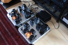
I made some progress on my 801A A2 amplifier using SpreadSpectrum's feedback methods. Since the circuit was going to need a breadboard anyway, I decided to put together a reusable prototyping board, I combined two projects into one.
I finished the board a few days ago and finished a single channel of the amplifier today. It uses plate-cathode NFB from the 801A to EF37A, buffered by a PMOS. The EF37A is loaded by a 390K resistor. The screen is regulated by a VR105 glow tube. Cap coupled to a parallel 6BX7 cathode follower, biased by a TL431 shunt regulated negative supply. It is direct coupled to the 801A grid, so setting the bias / cathode voltage of the 6BX7 biases the 801A. It is a near 0Vg1 bias point, comes out to around 320V 55mA. I think there is a schematic some pages back that shows the idea, I'll post an updated one at some point, but it has been a long day! 😀

Output Z in this iteration is 1.7ohm, which is great, hit one target on the first go around.
Clipping starts beyond 6.3W into 8ohms.
THD is higher than expected, 1W into 8ohm spectrum below, which I attribute to the open-loop gain of the EF37A being much lower than simulated, so that is what I will be investigating next. The harmonic spectrum, however, is favorable, so even as is I feel confident the sound will be pleasing.

Here is the frequency response.

Between the thoriated tungsten filament of the 801A and the glow tube, it is a very glowy amplifier.

Lots more to do, but it's a start.
I finished the board a few days ago and finished a single channel of the amplifier today. It uses plate-cathode NFB from the 801A to EF37A, buffered by a PMOS. The EF37A is loaded by a 390K resistor. The screen is regulated by a VR105 glow tube. Cap coupled to a parallel 6BX7 cathode follower, biased by a TL431 shunt regulated negative supply. It is direct coupled to the 801A grid, so setting the bias / cathode voltage of the 6BX7 biases the 801A. It is a near 0Vg1 bias point, comes out to around 320V 55mA. I think there is a schematic some pages back that shows the idea, I'll post an updated one at some point, but it has been a long day! 😀
Output Z in this iteration is 1.7ohm, which is great, hit one target on the first go around.
Clipping starts beyond 6.3W into 8ohms.
THD is higher than expected, 1W into 8ohm spectrum below, which I attribute to the open-loop gain of the EF37A being much lower than simulated, so that is what I will be investigating next. The harmonic spectrum, however, is favorable, so even as is I feel confident the sound will be pleasing.
Here is the frequency response.
Between the thoriated tungsten filament of the 801A and the glow tube, it is a very glowy amplifier.
Lots more to do, but it's a start.
Last edited:
Not only are your finished products immaculate, but your prototyping is too!
If you want more gain for more feedback, that's not too hard with the CCS||Resistor trick.
Edit: Does this have the G3 bias on the EF37A to square up the knees? The harmonic profile looks good.
If you want more gain for more feedback, that's not too hard with the CCS||Resistor trick.
Edit: Does this have the G3 bias on the EF37A to square up the knees? The harmonic profile looks good.
Last edited:
Thanks! Yeah I did mess around with the CCS load in the first prototype, at the time I was not using the PMOS buffer and was leaving the cathode degenerated. I will probably revisit it since I have this all built out, might as well get it right, although I'm not terribly concerned about the highish distortion given it is predominantly H2. More important for me was getting a low output Z. Based on the open-loop gain of the EF37A, this is with ~11dB of feedback, whereas I had planned to be able to apply ~15dB.
We'll see how it sounds, should be able to get the second channel done today and have a listen.
I haven't tried squaring up the curves yet, I figured I would seem how the harmonics play out with a resistive load, fortunately they look good! One other thing I did that I thought was clever, for a new guy like me: I had some Tent Labs heater regulators lying around from a project I never finished. I found these have very good line regulation and I needed a way to apply some grid bias to the EF37A to dial in the operating point, given the variable Vgs of the PMOS. So I put 6.3VDC on the heaters of the EF37A, then ran one end through a bias pot to the grid, worked like a charm 😀
Here is a schematic of the amplifier circuit as it stands at the moment. I might be able to push the 6BX7 grid resistance to increase the gain, it is listed at 2Meg max in the datasheet for autobias, no spec on grid bias, so I opted for a little less than 1Meg.

Last edited:
Good afternoon Audio-addicts,
sorry for my late entrance......
Noted the A2 DHTSE name and i had to reply.
I use the eimac 35TG with much delight for years now. Not only they sound great; they last for ages ! Still using the first pair (not exaclty true because i broke one when in applied to much pressure to the grid or anode-connection). When they survive the transatlantic transport (50% crash for Gremlin reasons) they are workhorses for years to come.....
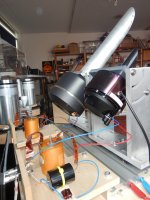
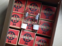
I LOVE the HK54, got my own stash of it (picture included with a 35TG and a 54HK side-by-side) as you can see into the filaments. Just as early 35T's and early 35TG's.
I run my 35TG's at 800V+ DC; completly A2 driven by a 6FJ7 trough a 4:1 step down interstage in parafeed-mode (A2 triodes like to see oomph...) .
Is everything A-ok ?! No.....of couse not this is an audio-adventure and currently these 35TG's are driving the bass-section only. Already got the new trannies for the amps (no air gap !) to get the max bass-response which is possible in parafed but first priority in my set set is a dedicated 1 watt amplifier for the highs (currently underway).
Regards, Reinout
sorry for my late entrance......
Noted the A2 DHTSE name and i had to reply.
I use the eimac 35TG with much delight for years now. Not only they sound great; they last for ages ! Still using the first pair (not exaclty true because i broke one when in applied to much pressure to the grid or anode-connection). When they survive the transatlantic transport (50% crash for Gremlin reasons) they are workhorses for years to come.....
I LOVE the HK54, got my own stash of it (picture included with a 35TG and a 54HK side-by-side) as you can see into the filaments. Just as early 35T's and early 35TG's.
I run my 35TG's at 800V+ DC; completly A2 driven by a 6FJ7 trough a 4:1 step down interstage in parafeed-mode (A2 triodes like to see oomph...) .
Is everything A-ok ?! No.....of couse not this is an audio-adventure and currently these 35TG's are driving the bass-section only. Already got the new trannies for the amps (no air gap !) to get the max bass-response which is possible in parafed but first priority in my set set is a dedicated 1 watt amplifier for the highs (currently underway).
Regards, Reinout
Attachments

Are you sure, that M3 FET only AC coupled to the negative supply? 😛Here is a schematic ...
In my pictures (with the box of HK54's) you see a 35TG and a HK54 side-by-side.
These tubes are almost equivalent. Almost as the 35T(G) needs 5V/4A for the filaments and the HK54 wants to have 5V/5A. For the rest they are the same.
There are numerous incarnations to the 35TG and HK54. The "topless" versions are the early ones of both factories.
But there are other differences as well: different anodes (coating), differnces in application of the Uranium glass (sealing), differences in top-structure, etc.
Besides these known Eimac 35T(G) and Heinz and Kauman 54 there are others that produces these triodes with almost the same specs (near-equivalent).
Lewis produced the 35T also (but like all Lewis tubes seriously less in quality).
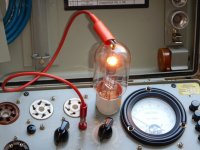
In the attached picture you can also see the SFR 556. A BEAUTY !! But i have only one (please please please....if someone has another orphan lets make this a pair....)
But also Eimac itself played for some time with this construction. See picture where you can see the UH35 on the right. Electrically the same but because of the heating the glass on top becomes overheated......which brought Eimac to the 35T/35TG where the anode-construction is lower in the glass.
Again, i have just a single/orphan...can somebody pair this to a second ?
Great (sounding) A2 tubes !
Regards,
Reinout
Included a picture of a Lewis 35T (left), SFR556 (middle) and Eimac UH35 (right). Compare those with the much more common HK54 and 35TG in the other picture
These tubes are almost equivalent. Almost as the 35T(G) needs 5V/4A for the filaments and the HK54 wants to have 5V/5A. For the rest they are the same.
There are numerous incarnations to the 35TG and HK54. The "topless" versions are the early ones of both factories.
But there are other differences as well: different anodes (coating), differnces in application of the Uranium glass (sealing), differences in top-structure, etc.
Besides these known Eimac 35T(G) and Heinz and Kauman 54 there are others that produces these triodes with almost the same specs (near-equivalent).
Lewis produced the 35T also (but like all Lewis tubes seriously less in quality).
In the attached picture you can also see the SFR 556. A BEAUTY !! But i have only one (please please please....if someone has another orphan lets make this a pair....)
But also Eimac itself played for some time with this construction. See picture where you can see the UH35 on the right. Electrically the same but because of the heating the glass on top becomes overheated......which brought Eimac to the 35T/35TG where the anode-construction is lower in the glass.
Again, i have just a single/orphan...can somebody pair this to a second ?
Great (sounding) A2 tubes !
Regards,
Reinout
Included a picture of a Lewis 35T (left), SFR556 (middle) and Eimac UH35 (right). Compare those with the much more common HK54 and 35TG in the other picture
Attachments

Are you sure, that M3 FET only AC coupled to the negative supply? 😛
Whoops! That's an error, here ya go euro21 😀

- Home
- Amplifiers
- Tubes / Valves
- Corona: An Ultra-Low Distortion A2 DHT SE Amp Prototype