George,
2 beads in series pretty much cured it into the dummy load.
Do you have recommendations on load testing? I'm looking to add some components to my dummy load to test my amps with difficult loads. I see some recommendations to add a 2uF cap in parallel to approximate a worst-case capacitive load from an ESL. Do you do any testing like that on your amps?
I want to make a test that's a little worse than a speaker would be expected to throw at it, but not ridiculous.
Ok, so I've had a chance to do a few measurements of output transformer differences. Both are 5k:8 transformers. Edcor is advertised as 25W, the EP transformer was spec'd at 40W.
First, winding resistances:
Edcor: 83.4 Ohm primary, 0.64 Ohm secondary
Electra-Print: 108.5 Ohm primary, 0.86 Ohm secondary
I attempted to take a crude measurement of primary inductance at 1W output by just decreasing frequency until the current waveform doubled in amplitude (my thinking was that primary inductive reactance would be approximately equal to 5k at that point). This was difficult to do, since I had to measure current on the high side with a differential probe to keep grid current out of the equation, which was a pretty noisy measurement with the 1 Ohm sense. My signal generator is also a cheap digital unit only adjustable in 1Hz increments. The jumps get to be quite large at low frequencies. I did my best and came up with:
Edcor: 40H
EP: 53H
I'll post pics of primary voltage vs secondary voltage at various frequencies for the two transformers in two subsequent posts to keep them separate.
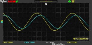
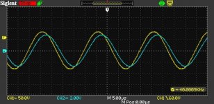
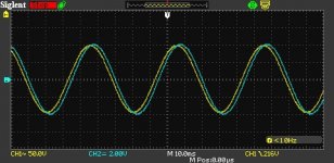
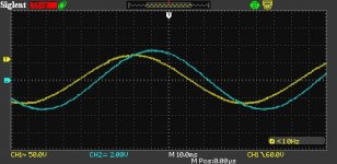
Here are some screen captures of the Electra-Print transformer being driven by the amp. Yellow is primary voltage, blue is secondary.
8Hz, 1kHz, 27kHz, and 10kHz square wave.
8Hz, 1kHz, 27kHz, and 10kHz square wave.
Attachments
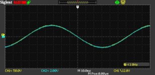
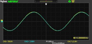
Here are some measurements at 8Hz, 20Hz, 40kHz, and 10kHz square wave that I made with the Edcor before removing it.
The EP has less high end, but pretty much no phase shift between primary and secondary at 8Hz.
Edcor does better at HF. I'm noticing that the secondary amplitude is larger than the primary amplitude at LF (through sheer accident, when scaled on this screen, they lay exactly on top of one another at midband).
Attachments
An analog 400mV/A output safer alternative to probe current SparkFun Current Sensor Breakout - ACS723 (Low Current) you may find useful. .
George,
Do you have recommendations on load testing? I'm looking to add some components to my dummy load to test my amps with difficult loads. I see some recommendations to add a 2uF cap in parallel to approximate a worst-case capacitive load from an ESL. Do you do any testing like that on your amps? I want to make a test that's a little worse than a speaker would be expected to throw at it, but not ridiculous.
I have been known to connect all sorts of stuff to the output of my amps since many of my customers do nearly as crazy unpredictable things with them.
After setting one of my cheap guitar amp OPT's on fire when my original series - parallel combination of heat sinked Radio Shack "non-inductive " audio test load resistors went open somewhere past 160 watts nearly 30 years ago, I bought a pair of 8 ohm 500 watt wirewound resistors.
I was reminded by a popular author of tube amp books that they were NOT non-inductive. I took one to work and measured it on a HP component analyzer. I don't remember the numbers now, but it worked out to less than 1% error at 20 KHz.
It is hard to predict every possible load that a speaker, especially a multi-way with a complex crossover network, can present to an amp. I built a box with a switch and some RLC networks inside to throw wrenches at the output of a typical tube amp. I built it long ago mostly for use with small guitar amps and my 1990's vintage 16 bit PC recording setup. It's not capable of much beyond 20 watts. It's somewhere here in a box that hasn't been opened since I left Florida.
It had a few different combinations inside, each with its own Radio Shack 20 watt load resistor. I do think that one was a fat cap across the resistor, and I know one was a direct copy of the "simulated guitar speaker" circuit that I traced out by cracking open a friends "Direct In" box. Guitar amp on one end, other end goes Directly Into the recording interface or mixing console. That thing had a lot of parts in it. A couple others were copies of crossover networks with a series RL in place of the speaker driver. Back in the 90's or 00's I had the idea of building a small 5 watt or so tube guitar amp and feeding its padded down output into an LM3886 chip amp. I never could get the right sound out of it, so it all wound up in a box.
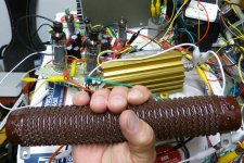
The gold colored resistor in the background is good for 120 watts if heatsinked. The big brown guy is rated for 500 watts.
Attachments
Last edited:
My dummy load is 4 2 Ohm Caddock TO-220 thick film resistors in series mounted on a big motor controller heatsink. It has fans that blow through the fins.
I think what I'll do is add a rotary switch onto my dummy load so I can put .1uF, .47uF, and 2uF in parallel to the 8 Ohms if I want to.
I've been reading more on the suggested 2uF ESL simulated capacitance and it seem this is a pretty extreme representation of these speakers since they have transformers in them and the winding resistances and leakage inductance would appear in series with the capacitance, which would serve to isolate the feedback circuit from the capacitive load.
Since my output transformer is outside the feedback loop, my output transformer would do the same, so I'm thinking the speaker being capacitive is probably less of a real problem than the parasitic capacitances in the output transformer itself, but it will be nice to have a load where I can test amplifier tolerance to capacitive load.
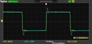
I ended up using three ferrite beads in series to completely tame the 1.1MHz gremlin.
With no beads, I get a constant, low level 1.1MHz oscillation. With 1 bead, I get some bursts of oscillation on 10Hz and below sine waves. With 2 beads, I get a very short oscillation at power-up. With 3 beads I get nothing under any conditions.
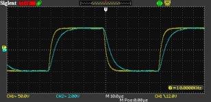
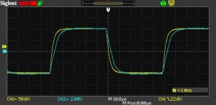
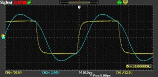
After resistive load testing, I tried adding capacitive loading to the secondary of the output transformer. I tested .1uF, .47uF, and 2uF in parallel with the load. At no point did the output of the feedback circuit look unstable in any way (yellow trace).
Now when I add capacitance to the secondary of the OT, I get some ringing due to the interactions of the parasitic elements in the OT and the external capacitance, but the feedback circuit is very much in control of the primary and looks very stable.
I think my previous prediction that the winding resistance and leakage inductance of the OT would isolate the feedback loop from the ill effects of capacitive loading turned out to be correct.
In the pictures you can see the three beads going to the OT and 1kHz and 10kHz square waves with 2uF loading. The waveform on the secondary of the OT gets ugly but the waveform on the primary isn't misbehaving.
With no beads, I get a constant, low level 1.1MHz oscillation. With 1 bead, I get some bursts of oscillation on 10Hz and below sine waves. With 2 beads, I get a very short oscillation at power-up. With 3 beads I get nothing under any conditions.
After resistive load testing, I tried adding capacitive loading to the secondary of the output transformer. I tested .1uF, .47uF, and 2uF in parallel with the load. At no point did the output of the feedback circuit look unstable in any way (yellow trace).
Now when I add capacitance to the secondary of the OT, I get some ringing due to the interactions of the parasitic elements in the OT and the external capacitance, but the feedback circuit is very much in control of the primary and looks very stable.
I think my previous prediction that the winding resistance and leakage inductance of the OT would isolate the feedback loop from the ill effects of capacitive loading turned out to be correct.
In the pictures you can see the three beads going to the OT and 1kHz and 10kHz square waves with 2uF loading. The waveform on the secondary of the OT gets ugly but the waveform on the primary isn't misbehaving.
Attachments
I have been known to connect all sorts of stuff to the output of my amps since many of my customers do nearly as crazy unpredictable things with them.
After setting one of my cheap guitar amp OPT's on fire when my original series - parallel combination of heat sinked Radio Shack "non-inductive " audio test load resistors went open somewhere past 160 watts nearly 30 years ago, I bought a pair of 8 ohm 500 watt wirewound resistors.
I was reminded by a popular author of tube amp books that they were NOT non-inductive. I took one to work and measured it on a HP component analyzer. I don't remember the numbers now, but it worked out to less than 1% error at 20 KHz.
It is hard to predict every possible load that a speaker, especially a multi-way with a complex crossover network, can present to an amp. I built a box with a switch and some RLC networks inside to throw wrenches at the output of a typical tube amp. I built it long ago mostly for use with small guitar amps and my 1990's vintage 16 bit PC recording setup. It's not capable of much beyond 20 watts. It's somewhere here in a box that hasn't been opened since I left Florida.
It had a few different combinations inside, each with its own Radio Shack 20 watt load resistor. I do think that one was a fat cap across the resistor, and I know one was a direct copy of the "simulated guitar speaker" circuit that I traced out by cracking open a friends "Direct In" box. Guitar amp on one end, other end goes Directly Into the recording interface or mixing console. That thing had a lot of parts in it. A couple others were copies of crossover networks with a series RL in place of the speaker driver. Back in the 90's or 00's I had the idea of building a small 5 watt or so tube guitar amp and feeding its padded down output into an LM3886 chip amp. I never could get the right sound out of it, so it all wound up in a box.
The gold colored resistor in the background is good for 120 watts if heatsinked. The big brown guy is rated for 500 watts.
Now im curious, have you had time to play around with the sweeps on the background? I have about 100 of the PL500/504 and still want to try screen drive someday. Sorry for muddling up the thread..
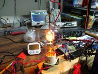
I've acquired a few of these tubes now and it is time to incorporate one in place of the 826. Then I'll work on a higher-voltage power supply to get the operating point where it needs to be to make some bigger power.
Beautiful! Watch your fingers and toes 😀
Dear SpreadSpectrum,
finally I simulated a cascoded 12AX7 version of your pentode gain stage: CED/UNSET/CORONA-like ECC88 hybrid cascoded driver
I've got 0,009% THD at 170 Vpp with 1.5 Vp at its input.
finally I simulated a cascoded 12AX7 version of your pentode gain stage: CED/UNSET/CORONA-like ECC88 hybrid cascoded driver
I've got 0,009% THD at 170 Vpp with 1.5 Vp at its input.
I have been falling down a A2 transmitting tube rabbit hole. I have a NOS pair of HK54, 50W cousin of the 3C24, I hadn't seriously considered a design around them, but starting to fantasize about the idea if I could find more pairs.

I traced more complete A1+A2 curves, shown with a 3K load line and 425V 100mA bias point, measured plate resistance is around 9K. Green lines are grid current from 0 to +120V on the grid.

Did some quick math to see what a "SpreadSpectrum Corona" feedback topology would require. With ~21dB of feedback and voltage gain of 200 from a pentode input, would get roughly a 3:1 damping factor with a 3K load, so that seems to be the minimum. From the curves, grid current at peak swing (125Va, +85Vg) is 45mA, around a 1.8K load. Would need a FET or a beefy cathode follower. A CF that came to mind is the EC360, but power supply current requirements would be very high, FET would be more reasonable. If my math is right, this would be around a 14W amplifier with a pretty reasonable B+ voltage.
Just some ramblings, might see if I can find more HK54.
I traced more complete A1+A2 curves, shown with a 3K load line and 425V 100mA bias point, measured plate resistance is around 9K. Green lines are grid current from 0 to +120V on the grid.
Did some quick math to see what a "SpreadSpectrum Corona" feedback topology would require. With ~21dB of feedback and voltage gain of 200 from a pentode input, would get roughly a 3:1 damping factor with a 3K load, so that seems to be the minimum. From the curves, grid current at peak swing (125Va, +85Vg) is 45mA, around a 1.8K load. Would need a FET or a beefy cathode follower. A CF that came to mind is the EC360, but power supply current requirements would be very high, FET would be more reasonable. If my math is right, this would be around a 14W amplifier with a pretty reasonable B+ voltage.
Just some ramblings, might see if I can find more HK54.
Last edited:
It looks like a really good operating point and should give great results.
Another option for output tube could be a 35T. HK54 seems to be about the same price as a 100TH. 35T can be had for $40 at vacuumtubes.net.
826 are also a good option (and with no exposed high voltage on top of the chassis), but a lot of them seem to be gassy so you have to be prepared to deal with returns/exchanges. And the datasheet calls for forced air cooling.
I just came across this output transformer: Single-Ended : VDV-HQ-5090-SES
It is huge, but it would be interesting to use in this feedback configuration, since primary DCR is 88 Ohm and secondary resistance is .07 Ohm. You could have a damping factor of like 40 without any feedback around the output transformer.
It is huge, but it would be interesting to use in this feedback configuration, since primary DCR is 88 Ohm and secondary resistance is .07 Ohm. You could have a damping factor of like 40 without any feedback around the output transformer.
It looks like a really good operating point and should give great results.
Another option for output tube could be a 35T. HK54 seems to be about the same price as a 100TH. 35T can be had for $40 at vacuumtubes.net.
826 are also a good option (and with no exposed high voltage on top of the chassis), but a lot of them seem to be gassy so you have to be prepared to deal with returns/exchanges. And the datasheet calls for forced air cooling.
Thanks, think it could be interesting. The 35T is another good option I was looking at, a little more available it seems. So far I was able to find another pair of HK54 for $40 each, not too bad for NIB 80 year old tubes.
As I have been cooking this idea today, I thought it might make some sense to sacrifice a little power for a simpler power supply, giving up the small amount of negative grid swing, load line like so, 375V 120mA at 90% dissipation.

Would still make around a 10-11W amplifier. I think using a cathode follower just doesn't make since practically, the bias plus grid current would make for a monstrous power supply. With a source follower, the gate could be biased positive via a decoupled voltage divider from B+, pretty simple.
I made a LTSpice model of the HK54, had some issues with it that Dmitry Nizh helped me troubleshoot, now all is working, below is my draft circuit with a 6AU6 input. Open loop gain from the 6AU6 is 210, could get more aggressive, but this gives a damping factor of about 3.5:1

Lundahl makes a 3K 120mA transformer, 27H primary inductance with 164ohm DCR, fits the bill pretty nicely.
Last edited:
That seems like a good deal for the HK54.
6AU6 is a good tube, but if I might suggest a look at the 6BN11, it has sharper knees which should lead to less odd harmonics. They are dirt cheap and look real neat with their open plate structure. If you prefer single tubes, the 6EW6 is the single version.
But I think the 6AU6 would work really well too.
The 6BN11/6EW6 curves are darn impressive, very sharp knees and high gain, could potentially double the open loop gain of the input stage, I see why you are using them! I will pick up a few to try out, thanks for the recommendation. I went through the datasheets of several other high gm sharp cutoff pentodes, not much else seems to come close. The 6JK6 looks interesting too.
Last edited:
Funny you should mention the 6EW6. I've been searching through my stock trying to find some 6AH6s and came across the 6EW6. Right now I'm prototyping something with the 6CB6 but the few I have are very microphonic. The structure of the 6CB6 looks like a shorter 6AH6/6EW6.
Well, for me looks are a significant factor so I like the glowing heater wire on the top that goes between the two cathodes and the open plate structure so you can see the grids and the cathodes. The high-ish gain allows me to really design whatever gain I want with my choice of load. Right now, the Corona bench design has like 35dB of feedback (IIRC) with the 1M||CCS plate load on the 6BN11.
I also kind of like the idea of taking compactron tubes which were the very last generation of tubes and pairing them up with some of the oldest tube designs that I can get my hands on for a reasonable price. I'm sure nobody ever did that in the tube days, and I like doing things in ways that haven't been done.
I also kind of like the idea of taking compactron tubes which were the very last generation of tubes and pairing them up with some of the oldest tube designs that I can get my hands on for a reasonable price. I'm sure nobody ever did that in the tube days, and I like doing things in ways that haven't been done.
Attachments
- Home
- Amplifiers
- Tubes / Valves
- Corona: An Ultra-Low Distortion A2 DHT SE Amp Prototype