Hi 🙂 Thanks for fine works
@SpreadSpectrum
could You post some transfer measurements with phase? Please.
what is primary inductance of Electra-Print OT you are using?
@SpreadSpectrum
could You post some transfer measurements with phase? Please.
what is primary inductance of Electra-Print OT you are using?
Hi, here's an article in stereophile about the circuit they use to occasionally represent loudspeaker loads when testing amplifiers. https://www.stereophile.com/reference/60/index.htmlZout is dependent on the output transformer used. The Edcor had lower winding resistances so Zout was about 0.7 Ohm. I'm currently using an Electra-Print transformer and Zout is closer to 1 Ohm but still below.
There really is no "final schematic" since I still haven't built it into a chassis yet. This is just a series of experiments, but the amplifier I will build will probably be a circuit like in post 354 and I'll make it reconfigurable for the various output tubes I tested in this thread. I'll probably make a second amp for the 826s since they require significantly lowered voltages and I'll use the Edcor transformers in that one. Some people may hate that I used an op-amp follower to drive the input tube cathode. The distortion with the p-channel fet follower was almost the same but it was easier to tame the 10kHz square wave with the op-amp follower and the end result was better. I personally don't have a problem with an LM4562 follower in my audio path since all my music has already passed through many, many NE5532s in the studio, but I know many in this forum would not approve.
The drawback to this approach is that there is no feedback around the transformer, so whatever happens there remains uncorrected. But it turns out that if you drive them from a low source impedance they add almost no distortion at midband. The misbehaviors will be at the frequency extremes. I think a few dB of feedback around the transformer would greatly improve things but I haven't gotten there yet. I'm currently working on an Arduino microprocessor bias controller for the amp that I'll probably share the code for here when I'm done.
I have not measured distortion with a speaker. I'd like to build a simulated speaker load at some point so I can do some tests like that and not have to listen to test tones.
I have measured output waveform RMS voltage while listening to music and it looks like even fairly cranked I'm at 1W or so. My test speakers are pretty efficient, though.
Maybe something like that will work?
And by the way I don't have much objection to using a couple of solid-state components, since like you pointed out my music source ie DAC is solid-state anyway. The main use for the amp is to take the low wattage output of the DACs and buffer with as little distortion as possible to drive my speakers. I just happen to like using vacuum tubes for the main amp that's all.
Last edited:
I haven't had the time. I've never done measurements like that so I'd have to figure out how to get set up first.Hi 🙂 Thanks for fine works
@SpreadSpectrum
could You post some transfer measurements with phase? Please.
what is primary inductance of Electra-Print OT you are using?
I'd like to build something like that some day. I think John Stewart on the forum here had a simulated speaker load that was a little simpler.Hi, here's an article in stereophile about the circuit they use to occasionally represent loudspeaker loads when testing amplifiers. https://www.stereophile.com/reference/60/index.html
Maybe something like that will work?
And by the way I don't have much objection to using a couple of solid-state components, since like you pointed out my music source ie DAC is solid-state anyway. The main use for the amp is to take the low wattage output of the DACs and buffer with as little distortion as possible to drive my speakers. I just happen to like using vacuum tubes for the main amp that's all.
The main concern I have is whether a speaker would ever cause the amp to misbehave, so I'm not necessarily looking for a realistic speaker model. I'd like to just see if the amp is good and stable into a somewhat capacitive or inductive load (to the degree that a worst-case speaker could present).
I think capacitive load is usually the bigger concern for this kind of feedback circuit. I did have issues at first with the Electra-Print output transformers. I assume they have bigger primary capacitance than the Edcors because I saw signs of lower level transient oscillations (~5MHz) that weren't there before. I put a few ferrite beads between the output tube plate and the transformer winding and they went away. I think it just needed enough inductance to isolate the capacitance from the feedback circuit at those frequencies. The ferrite beads serve the same purpose as the big air-core inductor in a solid-state amp.
I also tried putting capacitors in parallel with the 8-Ohm test load. The amp was totally stable with those. I went all the way up to 2.2uF. 10kHz square wave was very distorted but I would expect that with all of the parasitic elements of the OT and the load capacitance sending energy back and forth. No tendency to oscillate at all. I think the leakage inductance of the OT shields the feedback circuit from really any realistic capacitive load on the secondary of the OT.
The biggest issue with the current circuit is bias drift in the input stage. Since my B+ is just an active ripple reject circuit with no regulation, it varies with line voltage. Since the input stage cathode is biased to a fraction of B+ through the op-amp, small variations of bias occur over time and the huge gain of that stage makes the plate drift all over the place. So I'm working on a simple Arduino microprocessor-based bias controller for that stage that will measure B+ and calculate necessary grid bias, and then measure and adjust over time if necessary. Also, I like to have a fault-monitor circuit that can shut the amp down if necessary and a microprocessor works well for that. While I'm at it, I might as well use the microprocessor to maintain output tube bias, and now I'm thinking that rather than set a simple bias current, I could also have a maximum plate power limit so that if line voltage climbs too high I could dial back current in the output stage. As you can see I've got a real requirements creep problem and no customer to blame for it.
Excellent I like the idea of (1) opamp to regulate the B+and stabilise the operating points. (2) a small micro-controller to do the start-up and safety protection. Have you seen pete millet's 813SE, he has a micro-controller and a adc to monitor things http://www.pmillett.com/813_se_triode_amps.htmI'd like to build something like that some day. I think John Stewart on the forum here had a simulated speaker load that was a little simpler.
The main concern I have is whether a speaker would ever cause the amp to misbehave, so I'm not necessarily looking for a realistic speaker model. I'd like to just see if the amp is good and stable into a somewhat capacitive or inductive load (to the degree that a worst-case speaker could present).
I think capacitive load is usually the bigger concern for this kind of feedback circuit. I did have issues at first with the Electra-Print output transformers. I assume they have bigger primary capacitance than the Edcors because I saw signs of lower level transient oscillations (~5MHz) that weren't there before. I put a few ferrite beads between the output tube plate and the transformer winding and they went away. I think it just needed enough inductance to isolate the capacitance from the feedback circuit at those frequencies. The ferrite beads serve the same purpose as the big air-core inductor in a solid-state amp.
I also tried putting capacitors in parallel with the 8-Ohm test load. The amp was totally stable with those. I went all the way up to 2.2uF. 10kHz square wave was very distorted but I would expect that with all of the parasitic elements of the OT and the load capacitance sending energy back and forth. No tendency to oscillate at all. I think the leakage inductance of the OT shields the feedback circuit from really any realistic capacitive load on the secondary of the OT.
The biggest issue with the current circuit is bias drift in the input stage. Since my B+ is just an active ripple reject circuit with no regulation, it varies with line voltage. Since the input stage cathode is biased to a fraction of B+ through the op-amp, small variations of bias occur over time and the huge gain of that stage makes the plate drift all over the place. So I'm working on a simple Arduino microprocessor-based bias controller for that stage that will measure B+ and calculate necessary grid bias, and then measure and adjust over time if necessary. Also, I like to have a fault-monitor circuit that can shut the amp down if necessary and a microprocessor works well for that. While I'm at it, I might as well use the microprocessor to maintain output tube bias, and now I'm thinking that rather than set a simple bias current, I could also have a maximum plate power limit so that if line voltage climbs too high I could dial back current in the output stage. As you can see I've got a real requirements creep problem and no customer to blame for it.
By the way have you measured the distortion numbers you quoted in your experiments with the 211 and 100TH other than 1kHz ie over some frequency range? Ideally the amp has less than 0.1% over 100Hz to 15kHz. Not sure if that's possible at all.
Last edited:
Hi,I've been trying to follow a Douglas Self "blameless" approach to this amplifier and not add complexity where it doesn't improve system performance. I'm trying to follow the biggest source of system distortion and minimize it.
I've determined that the mosfet follower with resistor load @15mA is good enough. In fact, I cannot see any system-level changes even with fairly big changes to this stage.
I've tried various output tubes and have a good idea what works best. The higher mu tubes seem to be working best at the moment but that may change as I optimize the input stage.
I played a lot with operating points on the input stage and this has very large effects on the overall amplifier distortion. The input stage is clearly a place where further optimization could occur. I get best results at higher plate voltages and about 65V on the screen and 4mA anode current. I've been abusing the plate voltage rating a bit and idling the input stage at 350V. This gets distortion down to 2.5%@75Vrms output. This seems pretty high, but remember this stage also brings 65dB of gain to the table.
I imagine that there is a fair amount of distortion cancellation between the input stage and output stage, and I think there is probably a sweet spot for nulling out distortion. I don't think I've reached that point yet; the input stage is still the controlling factor. As it stands, the overall amplifier distortion profile is a 2nd harmonic dominant waterfall at all power levels up to clipping. I'm very happy with the results so far.
This is a summary of my latest tests with the new input tube operating point:
100mW: 0.017%
500mW: 0.013%
1W: 0.015%
2W: 0.018%
5W: 0.028%
10W: 0.037%
20W: 0.042%
30W: 0.10%
I want to try a folded cascode input stage and see where that lands me. It's possible that it will have less distortion but that this will lead to more system distortion if there is less cancellation between the two stages. I won't know until I try. But try I will.
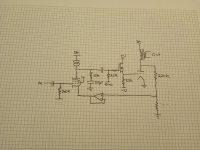
Here's a more current schematic of what I've got going:
View attachment 1007019
I am thinking of running some circuit sims with the 211 tube. If you don't mind sharing what's the value of the B+ you use and what's the bias. And what FETs did you end up using? Also what's the +V and -V you use for the 211 and 826 case?
I'm running the 211 at 622V and 112.5mA. B+ for the 6BN11 is 500V. +V and -V for the mosfet grid driver is currently at +144V and -144V (I used cheap 48V switchers stacked to make those rails for this experimental amp). If you use a higher gain output tube like the 826, those rails can be reduced. I don't remember how much lower they were when I was running the 826, but I just drew a load line and looked at how much grid drive it would need and gave it some headroom.
The bias voltage needed for the mosfet gate and 6BN11 grid are going to be highly dependent on the particulars of the model you use for simulation. I think the 6BN11 bias was good at ~4.5V (plate was 325V or so) and I think bias on the gate of the mosfet was just a few volts negative. You'll have to play with that in the sim to find the right values.
The p-channel fet on the 6BN11 cathode was an FQP3P50 and I tried a few n-channel devices for the 211 grid driver. I think there is an FQPF4N90 in there right now.

I have started down this road a few times using a Teensy microcontroller board, but never finished a working design. My "feature" list is also growing. One thing that I discovered back in my 2008 design that won a prize in a Microchip / Circuit Cellar contest was that it is best to feed an audio signal into the controller and set a threshold for determining when no audio signal is present. You don't want to measure idle current when a big bass transient is playing, and the usual low lass filter doesn't work if someone is cranking Pink Floyd at full tilt.. So I'm working on a simple Arduino microprocessor-based bias controller for that stage that will measure B+ and calculate necessary grid bias, and then measure and adjust over time if necessary. Also, I like to have a fault-monitor circuit that can shut the amp down if necessary and a microprocessor works well for that. While I'm at it, I might as well use the microprocessor to maintain output tube bias, and now I'm thinking that rather than set a simple bias current, I could also have a maximum plate power limit so that if line voltage climbs too high I could dial back current in the output stage. As you can see I've got a real requirements creep problem and no customer to blame for it.
They make some hall effect chips with pretty good galvanic isolation like this https://www.monolithicpower.com/en/...sheet/lang/en/sku/MCS1803GS/document_id/5067/
I have used these chips before with success on voltages up to 650 volts. The mosfets need to be rated for the full supply voltage and it would be wise to put a series resistor and a shunt zener on your microcontroller input just in case something goes wrong. The "500 volt current monitor" circuit is on page 18 and this works best on the power supply side of the OPT where the supply voltage is stable. I have enclosed a power supply design example as well.Here's the current state of it. For now I'll do a bias button but silence detection will be the end goal. Also I'd like to sense plate current instead of cathode current. Do you have any chips to recommend for that?
https://www.analog.com/media/en/technical-documentation/data-sheets/ltc6101.pdf
Attachments
By the way how did you implement the 4mA constant current? Any detail will help provide some info about the impedance of the current source as seen by the anode of the 6BN11. ThanksI'm running the 211 at 622V and 112.5mA. B+ for the 6BN11 is 500V. +V and -V for the mosfet grid driver is currently at +144V and -144V (I used cheap 48V switchers stacked to make those rails for this experimental amp). If you use a higher gain output tube like the 826, those rails can be reduced. I don't remember how much lower they were when I was running the 826, but I just drew a load line and looked at how much grid drive it would need and gave it some headroom.
The bias voltage needed for the mosfet gate and 6BN11 grid are going to be highly dependent on the particulars of the model you use for simulation. I think the 6BN11 bias was good at ~4.5V (plate was 325V or so) and I think bias on the gate of the mosfet was just a few volts negative. You'll have to play with that in the sim to find the right values.
The p-channel fet on the 6BN11 cathode was an FQP3P50 and I tried a few n-channel devices for the 211 grid driver. I think there is an FQPF4N90 in there right now.
They are a depletion-fet cascode. 10M90S is the upper device and DN2540 is the lower device. The set resistor is a 750 Ohm resistor in parallel with a 10k trimmer. I find that the 10M90S/DN2540 cascode is better-behaved up to higher frequencies than any other combo I have tested.
That set resistor only works down to 3.5mA or so. You'd need something different for anything less than that.
Edit: Oh, and I use 499 Ohm gate stoppers on the two devices.
That set resistor only works down to 3.5mA or so. You'd need something different for anything less than that.
Edit: Oh, and I use 499 Ohm gate stoppers on the two devices.
Last edited:
Thanks!I have used these chips before with success on voltages up to 650 volts. The mosfets need to be rated for the full supply voltage and it would be wise to put a series resistor and a shunt zener on your microcontroller input just in case something goes wrong. The "500 volt current monitor" circuit is on page 18 and this works best on the power supply side of the OPT where the supply voltage is stable. I have enclosed a power supply design example as well.
https://www.analog.com/media/en/technical-documentation/data-sheets/ltc6101.pdf
I've been looking at chips like the TLP7920 or ADUM3190 and I'm wondering if I can just put a zener across the input side power supply pins and run some current through it from the HV supply with the right arrangement. There is also the AMC3301 that has its own isolated internal switcher but that's starting to get pretty expensive, but seems like it would be super simple to implement.
I bought a couple of TLP7920 on my last order just to check them out.
I've looked at the hall effect chips in the past and they seem geared for fairly high currents. Do you have any experience with them at tube output stage level currents? I'm worried measurements would end up noisy but haven't really looked hard at them to see if that would be the case.They make some hall effect chips with pretty good galvanic isolation like this https://www.monolithicpower.com/en/...sheet/lang/en/sku/MCS1803GS/document_id/5067/
I've looked at the hall effect chips in the past and they seem geared for fairly high currents. Do you have any experience with them at tube output stage level currents? I'm worried measurements would end up noisy but haven't really looked hard at them to see if that would be the case.
Yeah that was my concern as well, being on the low end and not having enough resolution. You could do the typical sense resistor in the plate supply but the circuit would have to be isolated and float at the potential.
Here's another thought, how about a sense resistor with an opto isolator across it? They have some with a linear transfer like the LOC111. You might waste a watt or two in heat though...
I though I'd throw an update on here with the "final" schematic that I have settled on for the build.
I settled on using the LM4562 follower to drive the input tube cathode because this allowed me to get DC conditions right to ground the grid resistor and control the input tube bias by varying the screen voltage. Also, the amp behaved better on square wave testing with the LM4562 over the p-channel FET follower. Otherwise, the op-amp follower and the p-channel FET behaved pretty much identically in distortion testing. I also set the overall gain of the amplifier to be higher by changing the bottom resistor in the feedback divider to 200 Ohms.
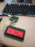
I have made significant progress on the amp/bias controller. I have the microprocessor displaying B+, output tube cathode current, approximate output tube plate power, input tube plate voltage, and it has an hours meter to keep track out tube hours.
I'm currently building the HV amplifier stage for the microprocessor DAC channels to control bias. I also just ordered parts to attempt plate current sensing so that I can more accurately calculate output tube plate power. Unfortunately, the 100TH grid draws about 18mA at idle so cathode sensing doesn't give you the info you need to determine plate power.
I've still got to implement some of the bias control code but I'm getting there.
I settled on using the LM4562 follower to drive the input tube cathode because this allowed me to get DC conditions right to ground the grid resistor and control the input tube bias by varying the screen voltage. Also, the amp behaved better on square wave testing with the LM4562 over the p-channel FET follower. Otherwise, the op-amp follower and the p-channel FET behaved pretty much identically in distortion testing. I also set the overall gain of the amplifier to be higher by changing the bottom resistor in the feedback divider to 200 Ohms.
I have made significant progress on the amp/bias controller. I have the microprocessor displaying B+, output tube cathode current, approximate output tube plate power, input tube plate voltage, and it has an hours meter to keep track out tube hours.
I'm currently building the HV amplifier stage for the microprocessor DAC channels to control bias. I also just ordered parts to attempt plate current sensing so that I can more accurately calculate output tube plate power. Unfortunately, the 100TH grid draws about 18mA at idle so cathode sensing doesn't give you the info you need to determine plate power.
I've still got to implement some of the bias control code but I'm getting there.
Attachments

@SpreadSpectrum
Hi, I would like to know if the LM4562 performs good after your tests, because I would like to use it to give feedback on the bottom of the driver of an SE.
It will have to handle 2-3 mA and give feedback to the cathode of the driver through a led diode.
Thanks
Roberto
Hi, I would like to know if the LM4562 performs good after your tests, because I would like to use it to give feedback on the bottom of the driver of an SE.
It will have to handle 2-3 mA and give feedback to the cathode of the driver through a led diode.
Thanks
Roberto
Hey SpreadSpectrum,
I've been lurking this thread for some time now. Thanks for all the work you've put into sharing your progress with us thus far. The amp looks very promising both aesthetically and in terms of performance.
Any updates to share? Has the amp come together for you into a finished piece yet?
Cheers
I've been lurking this thread for some time now. Thanks for all the work you've put into sharing your progress with us thus far. The amp looks very promising both aesthetically and in terms of performance.
Any updates to share? Has the amp come together for you into a finished piece yet?
Cheers
Thanks, metaphile!
I haven't built a finished product yet, but I listen to this thing all the time in the garage. I took a bit of a break on the development of this to fix up a couple of motorcycles. I'm actually back at it, just dug back in a few weeks ago.
Next thing I'm working on is finishing the Arduino system for detecting amp faults and adjusting bias for all tubes. I'll probably share progress on that in the next couple of weeks.
The other development is that I bought a pair of HQ-5090-SES Van der Veen output transformers. I'll be testing those out after I finish what I'm working on with the Arduino.
- Home
- Amplifiers
- Tubes / Valves
- Corona: An Ultra-Low Distortion A2 DHT SE Amp Prototype