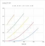
Oh, wow, those are very nice triode curves.
I've been looking at the mosfet I use to drive the grid. I have another that has the same capacitances but more transconductance. I might try that one in place of the Cree fet. I'm also going to try with resistive and current source load and try to quantify exactly what difference that makes.
I've been looking at the mosfet I use to drive the grid. I have another that has the same capacitances but more transconductance. I might try that one in place of the Cree fet. I'm also going to try with resistive and current source load and try to quantify exactly what difference that makes.
Last edited:
I traced those curves a few months back for a forum member, was really impressed, so couldn't pass up the lot when the opportunity struck. 1.8K plate resistance, mu 6.5, good stuff!
For what it's worth, when I was prototyping that 801A A2 amplifier, I tried both a resistive load and IXCP10M90S current sink on the 6BX7 cathode follower, same bias point. I didn't see any obvious measurable difference between the two (i.e., FR, THD, square wave), but I also tested subjectively and felt the sound strongly favored the current sink. YMMV of course, never tried it when I had the source follower in circuit.
For what it's worth, when I was prototyping that 801A A2 amplifier, I tried both a resistive load and IXCP10M90S current sink on the 6BX7 cathode follower, same bias point. I didn't see any obvious measurable difference between the two (i.e., FR, THD, square wave), but I also tested subjectively and felt the sound strongly favored the current sink. YMMV of course, never tried it when I had the source follower in circuit.
Ok, so I'm kind of surprised.
I set things up to measure distortion at 5W and took a baseline measurement. Then I doubled the standing current in the grid driver and took a measurement at 5W, then I did it again with triple the standing current.
All three measurements were indistinguishable. If the nonlinear grid current was the source of the high order distortion, I would really think that changing the standing current in the grid driver would affect its character in some way.
I'll take a look at the input stage next and see if the high-order stuff is originating there above a certain signal level. I avoided doing a distortion measurement earlier because the gain is just stupid high and it is obnoxious to deal with, but I'll do it now that I've got something to track down.
There has to be a reason that the higher harmonics are appearing with higher grid drive levels that the lower gain tube requires. However, it might not have anything to do with crossing the Vg=0 line.
Hi LordGwyn,
Thank you once again for tracing the triode curves for HY 69 (for me). I am in Bangladesh, could not buy HY 69 as yet. Where from you bought the tubes? Can you help me to get few HY 69.
All the best.
Thank you once again for tracing the triode curves for HY 69 (for me). I am in Bangladesh, could not buy HY 69 as yet. Where from you bought the tubes? Can you help me to get few HY 69.
All the best.
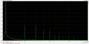
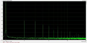
I've gone over the input stage and distortion measurements reveal that at the output level needed to drive the VT-127 to 5W, 2nd harmonic is dominant (by far), 3rd is low and 4th is barely detectable out of the noise floor. No other harmonics are detectable.
However, the way I'm testing distortion is not the way the stage runs in the amp. Instead of feeding a tiny input and having the stage amplify that to what output stage needs, there is a much larger common mode signal and the input stage is amplifying the difference between the input and the feedback signal.
My screen supply is referenced to ground so there is going to be some difference in operation. I've decided to rebuild that screen supply so that I can do a line of experimentation where I vary screen voltages and input stage idle currents to determine the best operating point. I also want to be able to reference the screen to the tube cathode and see if that helps performance.
First I'm going to try a grid driver mosfet with ~5X the transconductance of the Cree fet I'm using and see if that makes any difference.
So those will be the next steps.
I've been attempting to track down the source of the high-order harmonics in the amp.
1) I doubled and tripled the standing current in the grid driver mosfet. Distortion was exactly the same. I substituted a different mosfet with 5x more transconductance (FQPF4N90C). Also no difference. If the grid drive were the source of the high-order harmonics I would have expected the relative amplitudes of the harmonics to shift in some way but there was no change whatsoever with these grid driver modifications.
2) I constructed an adjustable screen supply for the input tube and varied screen voltage. Lowering from 115V to 75V lowered distortion of the tube and lowered the amplitude of higher harmonics at high levels considerably. When I ran this configuration in the full circuit, the high order harmonics were again identical to what they were before. 2nd and 3rd were slightly lower which gave THD results that were a little lower overall. I did try referencing the screen supply to both ground and the cathode. Interestingly, the cathode referenced supply gave a little less distortion at levels below 2W and the ground referenced supply gave less distortion at high powers. I expected that one would work better than the other across the board.
3) I swapped out the VT-127 for another sample. Relative amplitudes of the high-order harmonics are all different with the other sample.
I think the high-order harmonics are caused by the characteristics of the VT-127. I don't think there is any simple way to get rid of them.
I am making some good headway on optimizing the operating point of the input tube but I have to modify the screen supply to try lower voltages. Things were getting better and better as I went down to 75V
I've been trying to follow a Douglas Self "blameless" approach to this amplifier and not add complexity where it doesn't improve system performance. I'm trying to follow the biggest source of system distortion and minimize it.
I've determined that the mosfet follower with resistor load @15mA is good enough. In fact, I cannot see any system-level changes even with fairly big changes to this stage.
I've tried various output tubes and have a good idea what works best. The higher mu tubes seem to be working best at the moment but that may change as I optimize the input stage.
I played a lot with operating points on the input stage and this has very large effects on the overall amplifier distortion. The input stage is clearly a place where further optimization could occur. I get best results at higher plate voltages and about 65V on the screen and 4mA anode current. I've been abusing the plate voltage rating a bit and idling the input stage at 350V. This gets distortion down to 2.5%@75Vrms output. This seems pretty high, but remember this stage also brings 65dB of gain to the table.
I imagine that there is a fair amount of distortion cancellation between the input stage and output stage, and I think there is probably a sweet spot for nulling out distortion. I don't think I've reached that point yet; the input stage is still the controlling factor. As it stands, the overall amplifier distortion profile is a 2nd harmonic dominant waterfall at all power levels up to clipping. I'm very happy with the results so far.
This is a summary of my latest tests with the new input tube operating point:
100mW: 0.017%
500mW: 0.013%
1W: 0.015%
2W: 0.018%
5W: 0.028%
10W: 0.037%
20W: 0.042%
30W: 0.10%
I want to try a folded cascode input stage and see where that lands me. It's possible that it will have less distortion but that this will lead to more system distortion if there is less cancellation between the two stages. I won't know until I try. But try I will.
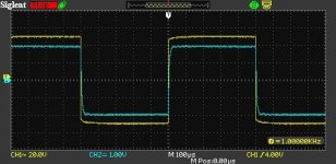
Here's a more current schematic of what I've got going:

I've determined that the mosfet follower with resistor load @15mA is good enough. In fact, I cannot see any system-level changes even with fairly big changes to this stage.
I've tried various output tubes and have a good idea what works best. The higher mu tubes seem to be working best at the moment but that may change as I optimize the input stage.
I played a lot with operating points on the input stage and this has very large effects on the overall amplifier distortion. The input stage is clearly a place where further optimization could occur. I get best results at higher plate voltages and about 65V on the screen and 4mA anode current. I've been abusing the plate voltage rating a bit and idling the input stage at 350V. This gets distortion down to 2.5%@75Vrms output. This seems pretty high, but remember this stage also brings 65dB of gain to the table.
I imagine that there is a fair amount of distortion cancellation between the input stage and output stage, and I think there is probably a sweet spot for nulling out distortion. I don't think I've reached that point yet; the input stage is still the controlling factor. As it stands, the overall amplifier distortion profile is a 2nd harmonic dominant waterfall at all power levels up to clipping. I'm very happy with the results so far.
This is a summary of my latest tests with the new input tube operating point:
100mW: 0.017%
500mW: 0.013%
1W: 0.015%
2W: 0.018%
5W: 0.028%
10W: 0.037%
20W: 0.042%
30W: 0.10%
I want to try a folded cascode input stage and see where that lands me. It's possible that it will have less distortion but that this will lead to more system distortion if there is less cancellation between the two stages. I won't know until I try. But try I will.
Here's a more current schematic of what I've got going:

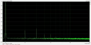
Here is a summary of the distortion measurements with a 211:
100mW: 0.016%
500mW: 0.013%
1W: 0.015%
2W: 0.019%
5W: 0.025%
10W: 0.037%
20W: 0.081%
22.6W: 0.10%
30W: 0.78%
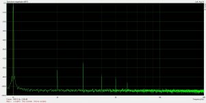
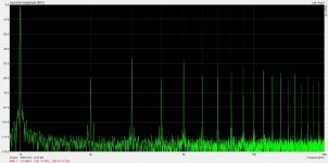
The spectrum is 3rd dominant until pretty high levels, where it becomes 2nd harmonic dominant. I suspect that the 2nd harmonic distortion from the 211 is cancelling very well with the 2nd harmonic that is produced by the 6BN11 driver. I lowered B+ to 620V to provide an operating point optimized for the 211's 75W plate dissipation limit. I ran the tube at 110mA. From looking at the grid waveform at clipping, it looks like a slightly lower B+ and slightly higher current operating point would be optimal. The tube hits cutoff before it starts hitting saturation.
The 211 looks like a really good tube. The plate is able to be pulled nice and low before it hits saturation and stops. It is a really great option if you want to build a transmitter tube A2 amp with a comparatively low plate voltage. 100T variants will get me 40W audio output with 750V on the plate, but a 211 will get me 30W with probably 600V or so.
100mW: 0.016%
500mW: 0.013%
1W: 0.015%
2W: 0.019%
5W: 0.025%
10W: 0.037%
20W: 0.081%
22.6W: 0.10%
30W: 0.78%
The spectrum is 3rd dominant until pretty high levels, where it becomes 2nd harmonic dominant. I suspect that the 2nd harmonic distortion from the 211 is cancelling very well with the 2nd harmonic that is produced by the 6BN11 driver. I lowered B+ to 620V to provide an operating point optimized for the 211's 75W plate dissipation limit. I ran the tube at 110mA. From looking at the grid waveform at clipping, it looks like a slightly lower B+ and slightly higher current operating point would be optimal. The tube hits cutoff before it starts hitting saturation.
The 211 looks like a really good tube. The plate is able to be pulled nice and low before it hits saturation and stops. It is a really great option if you want to build a transmitter tube A2 amp with a comparatively low plate voltage. 100T variants will get me 40W audio output with 750V on the plate, but a 211 will get me 30W with probably 600V or so.
Attachments


Hello. Sorry for my English, great results, I have been building circuits for years (A1 triode) where the first stage cancels the harmonics of the power stage and I can see that you have the same effect at maximum power, a large increase in higher-order harmonics, where their level is still low compared to others systems, but very audible, it means that these systems have such a character. Take a distortion measurement, only connect a loudspeaker instead of a resistor, for me the level of odd distortions has decreased and the total distortions have also decreased. Successful in further work.
It is interesting that the best results were with the 100TH and the 211. THD was almost the same between the two but the 100TH was the tube with the highest gain that I tested, and the 211 had the lowest gain. VT127A had the highest high-order content of them all, and 327A was closer to 100TH in that regard. They all have their individual character.
The 100TH had quite a bit lower high-order distortions than the 211 for whatever reason. It makes me wonder if an 811A wouldn't make a great 300B killer in this configuration.
If I do a distortion measurement with a speaker, it will have to be pretty low power, but I could give it a try.
I have put the RMS meter on the output of the amp while I am playing music and it seems like ~1W average output power is extremely loud. These 30-40W transmitter tube amps circuits are barely breaking a sweat when I use them.
I did measurements on speakers (Telefunken TL90) up to 10W, you will see what the THD looks like when you have an RLC load. I only deal with SE A1 systems, so I will not help and advise you, so only tests are left. Good luck.
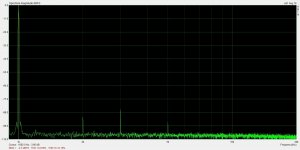
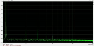
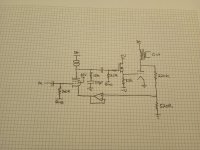
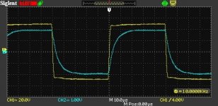
I've attached the latest experimental configuration along with square wave performance. I tested out an op-amp (LM4562) follower driving the cathode of the input stage. There is slightly less distortion overall but high frequency behavior is significantly better. Playing around with the RC network on the plate of the input stage, I was able to achieve a pretty good square wave response. The yellow trace is the primary of the output transformer, blue is the secondary.
This is probably a case where the output transformer design could be optimized for the very low primary driving impedance (<10Ohm) to get better HF performance for the amp. The current output transformer is an Electra-Print. Jack seemed very skeptical of what I planned on achieving as far as driving impedance and was somewhat argumentative so I doubt this transformer was optimized for the application, even though I really tried to convey exactly how it would be used.
This is probably a case where the output transformer design could be optimized for the very low primary driving impedance (<10Ohm) to get better HF performance for the amp. The current output transformer is an Electra-Print. Jack seemed very skeptical of what I planned on achieving as far as driving impedance and was somewhat argumentative so I doubt this transformer was optimized for the application, even though I really tried to convey exactly how it would be used.
Attachments
That sounds like Jack. I had a similar experience trying to order a transformer for something far less exotic. He explained to me that he feels Electra-Prints reputation could be compromised if someone uses his transformers in a questionable design (from his perspective). Also, if you want your amp in his "wall of fame", measurements are required for approval! Too funny.
On the other hand, I'm sure he would get plenty of people who would blame him for their poor specifications. It's probably not an easy business to be in.
If I could find a good supplier for small quantities of the necessary parts, I might try making a transformer myself. I probably wouldn't fail too badly with the late Patrick Turner's website and this forum to guide me.
If I could find a good supplier for small quantities of the necessary parts, I might try making a transformer myself. I probably wouldn't fail too badly with the late Patrick Turner's website and this forum to guide me.
Wow I just stumbled across this page while looking for a low distortion 845 or 811 or 211 amp. Amazing performance numbers for the 211. What's teh output impedance of the amp at the secondary coil? less than 1 Ohm? Amazing.Here is a summary of the distortion measurements with a 211:
100mW: 0.016%
500mW: 0.013%
1W: 0.015%
2W: 0.019%
5W: 0.025%
10W: 0.037%
20W: 0.081%
22.6W: 0.10%
30W: 0.78%
The spectrum is 3rd dominant until pretty high levels, where it becomes 2nd harmonic dominant. I suspect that the 2nd harmonic distortion from the 211 is cancelling very well with the 2nd harmonic that is produced by the 6BN11 driver. I lowered B+ to 620V to provide an operating point optimized for the 211's 75W plate dissipation limit. I ran the tube at 110mA. From looking at the grid waveform at clipping, it looks like a slightly lower B+ and slightly higher current operating point would be optimal. The tube hits cutoff before it starts hitting saturation.
The 211 looks like a really good tube. The plate is able to be pulled nice and low before it hits saturation and stops. It is a really great option if you want to build a transmitter tube A2 amp with a comparatively low plate voltage. 100T variants will get me 40W audio output with 750V on the plate, but a 211 will get me 30W with probably 600V or so.
Is the circuit on post 354 or 347 the final schematic? And all without any global feedback from transformer secondary? Just wonder if cathode feedback will help the distortion characteristics & damping factor at all. By the way what transformers are you using for the 211 amp?
Have you since measured the distortion when driving a speaker load at 100mW, 500mW, 1 watt and 2 watts. I think these are the levels suitable for normal average listnening even with low efficiency 85dB speakers.
@SpreadSpectrum
how do you usually set the SE amps working? Hit cutoff before saturation, or both together?
how do you usually set the SE amps working? Hit cutoff before saturation, or both together?
Zout is dependent on the output transformer used. The Edcor had lower winding resistances so Zout was about 0.7 Ohm. I'm currently using an Electra-Print transformer and Zout is closer to 1 Ohm but still below.Wow I just stumbled across this page while looking for a low distortion 845 or 811 or 211 amp. Amazing performance numbers for the 211. What's teh output impedance of the amp at the secondary coil? less than 1 Ohm? Amazing.
Is the circuit on post 354 or 347 the final schematic? And all without any global feedback from transformer secondary? Just wonder if cathode feedback will help the distortion characteristics & damping factor at all. By the way what transformers are you using for the 211 amp?
Have you since measured the distortion when driving a speaker load at 100mW, 500mW, 1 watt and 2 watts. I think these are the levels suitable for normal average listnening even with low efficiency 85dB speakers.
There really is no "final schematic" since I still haven't built it into a chassis yet. This is just a series of experiments, but the amplifier I will build will probably be a circuit like in post 354 and I'll make it reconfigurable for the various output tubes I tested in this thread. I'll probably make a second amp for the 826s since they require significantly lowered voltages and I'll use the Edcor transformers in that one. Some people may hate that I used an op-amp follower to drive the input tube cathode. The distortion with the p-channel fet follower was almost the same but it was easier to tame the 10kHz square wave with the op-amp follower and the end result was better. I personally don't have a problem with an LM4562 follower in my audio path since all my music has already passed through many, many NE5532s in the studio, but I know many in this forum would not approve.
The drawback to this approach is that there is no feedback around the transformer, so whatever happens there remains uncorrected. But it turns out that if you drive them from a low source impedance they add almost no distortion at midband. The misbehaviors will be at the frequency extremes. I think a few dB of feedback around the transformer would greatly improve things but I haven't gotten there yet. I'm currently working on an Arduino microprocessor bias controller for the amp that I'll probably share the code for here when I'm done.
I have not measured distortion with a speaker. I'd like to build a simulated speaker load at some point so I can do some tests like that and not have to listen to test tones.
I have measured output waveform RMS voltage while listening to music and it looks like even fairly cranked I'm at 1W or so. My test speakers are pretty efficient, though.
I typically set the operating point to hit both together, then I verify by monitoring the output tube grid voltage on a scope when I test at high power. I should see spikes developing on the positive and negative sides of the grid waveform symmetrically as I hit clipping.@SpreadSpectrum
how do you usually set the SE amps working? Hit cutoff before saturation, or both together?
- Home
- Amplifiers
- Tubes / Valves
- Corona: An Ultra-Low Distortion A2 DHT SE Amp Prototype