Nice to hear you're still listening to and enjoying the amp - looking forward to your next update.
Ok, here's the promised update on the Arduino bias/monitor system:
I've got the Arduino Nano Every with a 4-channel DAC peripheral board connected. This drives a high voltage amplifier chip on the left so that I can generate controllable screen voltages for the input tube and grid bias voltages for the output tubes. I was afraid because the chip package is so small and all of the pins so close together, so I conformal coated the chip to help insulate the pins/pads from one another (+144V and GND are right next to each other). It seems to work and has survived a bunch of power cycles.
For the output tubes, I started out with a simple cathode current sense resistor, but this doesn't tell me what the plate current of the output tube is since grid current is in there too. The board on the right is the TLP7920 and some circuitry to scale the output to a voltage that starts at 0V and increases with increasing current on the input. One difficulty I had with the TLP7920 was with the 5V supply on the high voltage side. I used (abused?) a Meanwell switching supply with an isolated output. The datasheet indicated that the isolation was tested with some pretty high voltages but stopped short of stating that you could float the output at 750V in a design. No smoke has come out so far. The other alternative that I considered was a Zener/resistor string but that would waste quite a bit of power.
I also had another problem. Sensing current on the high-voltage side means that my feedback resistor is part of the current measurement. I RC filtered the output and subtracted the average resistor current through the resistor in software. So now I have plate current, HV measurement, and a calculated plate power on the display for the output tube.
Next step is to start calculating bias adjustments. That's the part of the software I'm working on now. At first, I'll have a button to initiate bias adjustments but later I'd like to detect silence at the input and calculate/apply adjustments from measurements made then.
Attachments


Very impressive 👏 The critters on the bench are multiplying!
I like how this project diverges from the more common single-ended, no/low feedback, analog-only design variety and applies contemporary digital electronics and a healthy lack of fear of feedback to extract the best possible performance out of those beautiful glowing transmitter tubes. It feels as though you're approaching a truly no-compromises outcome, and I'm enjoying following the journey of the project.
I like how this project diverges from the more common single-ended, no/low feedback, analog-only design variety and applies contemporary digital electronics and a healthy lack of fear of feedback to extract the best possible performance out of those beautiful glowing transmitter tubes. It feels as though you're approaching a truly no-compromises outcome, and I'm enjoying following the journey of the project.
Just as a short aside, not sure how many saw member Mark Paanakker's article (attached to his post). His statement that if used, a lot should be used was interesting.a healthy lack of fear of feedback
All of the low rp transmitting triodes are pretty ridiculously expensive. This approach is a good way to take the high rp tubes and make a good amp with them. That's how the idea was born; I wanted to build an amp with a neat-looking transmitting tube that I could afford. I did SE because I have no use for a 500W+ amp and I hadn't done an SE amp yet.I like how this project diverges from the more common single-ended, no/low feedback, analog-only design variety and applies contemporary digital electronics and a healthy lack of fear of feedback to extract the best possible performance out of those beautiful glowing transmitter tubes. It feels as though you're approaching a truly no-compromises outcome, and I'm enjoying following the journey of the project.
I've finally accomplished some things on this project.
I finished the Arduino bias control/monitoring system. It works like a champ and I love having a display that tells me everything going on in the amp. I'll start a thread on that when I'm ready to write it all up (I'll post a link in this thread for those following). I'll share the source code for anyone that wants to use it for something similar.
I also got the HQ-5090 output transformer in the circuit and tested it some. I swept frequency response of the amp at 1W. It was down 3dB at 40kHz, matching the datasheet. I swept it on the low end but it was still perfectly flat at 10Hz and I didn't really want to go below that. Datasheet says it should be 3dB down at 8Hz. I measured 1W distortion before (with Electra-Print OT) and after. It was very close but slightly lower with the HQ-5090. Difference was very small and might be within the margin of repeatability of my measurements. I measured Zout at 0.63 Ohm (12.7 damping factor). Pretty respectable, but I knew it would be with these low winding resistances. This is probably the perfect type of output transformer for this amp. It is almost optimal. It is gapped for more standing current than I need but is otherwise pretty perfect.
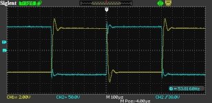
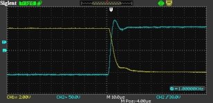
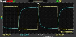
I have attached some square wave test results. I tested with an 8 Ohm purely resistive load and with 0.1uF, 0.47uF, and 2uF in parallel with the 8 Ohm resistor. Blue trace is the output tube plate and yellow trace is the output transformer secondary.
Unfortunately, I think the experimentation phase of this project is finished and I need to build it up in a chassis. I mean, I love experimenting so I'm actually kind of sad that part is over.
I finished the Arduino bias control/monitoring system. It works like a champ and I love having a display that tells me everything going on in the amp. I'll start a thread on that when I'm ready to write it all up (I'll post a link in this thread for those following). I'll share the source code for anyone that wants to use it for something similar.
I also got the HQ-5090 output transformer in the circuit and tested it some. I swept frequency response of the amp at 1W. It was down 3dB at 40kHz, matching the datasheet. I swept it on the low end but it was still perfectly flat at 10Hz and I didn't really want to go below that. Datasheet says it should be 3dB down at 8Hz. I measured 1W distortion before (with Electra-Print OT) and after. It was very close but slightly lower with the HQ-5090. Difference was very small and might be within the margin of repeatability of my measurements. I measured Zout at 0.63 Ohm (12.7 damping factor). Pretty respectable, but I knew it would be with these low winding resistances. This is probably the perfect type of output transformer for this amp. It is almost optimal. It is gapped for more standing current than I need but is otherwise pretty perfect.
I have attached some square wave test results. I tested with an 8 Ohm purely resistive load and with 0.1uF, 0.47uF, and 2uF in parallel with the 8 Ohm resistor. Blue trace is the output tube plate and yellow trace is the output transformer secondary.
Unfortunately, I think the experimentation phase of this project is finished and I need to build it up in a chassis. I mean, I love experimenting so I'm actually kind of sad that part is over.
Attachments
Hi 🙂 Thanks for fine works
@SpreadSpectrum
could You post some transfer measurements with phase? Please.
what is primary inductance of Electra-Print OT you are using?
You did significantly complicated measurements versus these simple and basic of transfer and phase... 🙂 And You can use the same equipnemt and Arta software too...I haven't had the time. I've never done measurements like that so I'd have to figure out how to get set up first.
...
I am just thinking loud:
Why in almost 99% diyers dont publish very simple measurements of frequency sweep transfer and phase? As the basic starting measurements.
AND no very simple and 30 sec to measure datas of Primary inductance of the OT?
.
These are the very welcome datas and very significant for diy community.
Without these simple datas somehow everything is 🙁
I haven't been able to figure out how to plot phase in Arta. I can do amplitude but I already described amplitude beyond the audio band. If you know how to do this in Arta, please describe. Maybe I'm just not getting it and need a little help to make that work.You did significantly complicated measurements versus these simple and basic of transfer and phase... 🙂 And You can use the same equipnemt and Arta software too...
I thought you meant plotting everything out from subsonic to ultrasonic, which my sound card is not going to do. The only way I have right now to make these measurements is eyeballing phase shifts on the scope, taking notes, and plotting. I could do that but I'm going to tweak the compensation to get less overshoot on the square wave first.
What value of capacitive load is good for testing amplifiers? I'll test no load and cap load after I tweak compensation to get less/no overshoot. I finally found my trimmer/cap test setup.How did it respond with no load, and with cap only loading?
From your schematic in post #377, and scope plots in #386, there is an identifiable 100kHz resonance on the plate waveform, which is your feedback take-off. I couldn't easily identify your scope-probe bandwidth, or your square-wave generator bandwidth - do you know them?
You have a 100kHz RC within the loop. Do you know the opamp bandwidth for unity gain?
Do you know your feedback level in dB? Perhaps tricky to check, as you would need to use the nominal idle bias level of the input cathode from a fixed bias.
Typically for GNFB amps, the output is checked with a few spot caps from say 1nF to 0.47uF, but that is all very ball-park, and sort of depends on the square wave response, as you don't have a gain-phase measurement setup.
Probes are 70MHz, scope is 50MHz, the opamp is an LM4562 with GBW product of 55MHz(typ) 45MHz(min). I will confirm the generator BW. It is just a cheap unit and I recall it being something like 800kHz.
I measured open-loop gain of the stages once and came up with the ratio of open-loop to closed-loop gain. I don't remember what output tube I did that for but I came up with something north of 30dB. This input stage has a lot of gain. I'll try to run that again so I can get a better number.
I measured open-loop gain of the stages once and came up with the ratio of open-loop to closed-loop gain. I don't remember what output tube I did that for but I came up with something north of 30dB. This input stage has a lot of gain. I'll try to run that again so I can get a better number.
Looks like I'm running about 25dB of feedback right now. I forgot I adjusted the feedback resistor ratio which cut the gain down to less than half of what it was. I just swept the generator and it looks to be 3dB down at 900kHz.
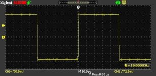
I adjusted the RC network to 100pF and 36.8k and got the square wave response below. I can try other capacitances later but ran out of time for tonight. I also attached the generator waveform for reference.
I adjusted the RC network to 100pF and 36.8k and got the square wave response below. I can try other capacitances later but ran out of time for tonight. I also attached the generator waveform for reference.
Attachments
@SpreadSpectrum Thanks for the updates!
Have you ever tried to apply differential feedback to your amps? Basically you scale down the output signal like you have done, and on the other side of the OPAMP you connect the input signal in order to have only the amplified distortion as OPAMP output, so as applied feedback.
Have you ever tried to apply differential feedback to your amps? Basically you scale down the output signal like you have done, and on the other side of the OPAMP you connect the input signal in order to have only the amplified distortion as OPAMP output, so as applied feedback.
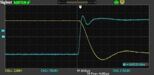
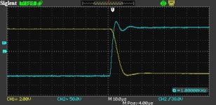
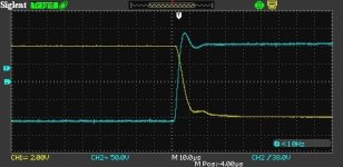
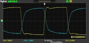
Here is 300pF and a 10k resistor. There is no overshoot but there is a dip after the leading edge. Is it better to try to round that bump off or is this pretty good?
I didn't have a dip in the square wave with the Electra-Print transformer loading the output tube plate...
The waveform on the secondary is definitely a bit smoother.
Edit: I have not tried differential feedback as you suggest. Gain would be pretty huge if I tried to apply it here. I'll definitely think about it.
Attachments
Thanks @SpreadSpectrum ! I really like the idea of your amp and results are indeed astonishing.
You and Tubelab are the ones that IMVHO have better integrated new technologies to bring SE tube amps a big step forward.
Concerning the differential feedback, I've succesfully used it in PP amps and I've bought the OPAMP you suggested here to apply feedback on the cathode of the driver (local negative feedback anode to g1 on the output pentode to triodify it + positive feedback from anode to anode to get a CCS-like loadline on the driver and minimize distortion + differential negative feedback on the cathode of the driver to iron the already low distortion and adapt the DF of the amp to the needs of the speaker), but I'm working on some speakers now and I've not started to work on this SE yet.
HiI haven't been able to figure out how to plot phase in Arta. I can do amplitude but I already described amplitude beyond the audio band. If you know how to do this in Arta, please describe. Maybe I'm just not getting it and need a little help to make that work.
I thought you meant plotting everything out from subsonic to ultrasonic, which my sound card is not going to do. The only way I have right now to make these measurements is eyeballing phase shifts on the scope, taking notes, and plotting. I could do that but I'm going to tweak the compensation to get less overshoot on the square wave first.
Thanks for answering.
.
Did You measure Primary inductance of Output transformer maybe?
Thanks 🙂
Just found this thread! Been wanting to try A2 for a while. Someday, I will! Followed a number of A2 threads here; pmillett and Michael Koster to name a few. Been collecting Eimac tubes for years for potential projects. Ran some 100TH & others in PP using Jack Iliano's driver transformer and an Edcor 100W 10K OPT (thanks Wavebourn!). Had to run the zirconium coated plates cherry red for a few hours to mop up gasses. Got to 100W but distortion products were a little high. Did not take notes back then, unfortunately.
Following and thanks for the great thread!

Following and thanks for the great thread!
Thanks, I'm going to build this one up into an amplifier like it is right now and I might try some experiments with the 826 output tubes along those lines before I build another amp for those tubes. I've got enough parts to make 2 great amps, but why make them the same?Concerning the differential feedback, I've succesfully used it in PP amps and I've bought the OPAMP you suggested here to apply feedback on the cathode of the driver (local negative feedback anode to g1 on the output pentode to triodify it + positive feedback from anode to anode to get a CCS-like loadline on the driver and minimize distortion + differential negative feedback on the cathode of the driver to iron the already low distortion and adapt the DF of the amp to the needs of the speaker), but I'm working on some speakers now and I've not started to work on this SE yet.
- Home
- Amplifiers
- Tubes / Valves
- Corona: An Ultra-Low Distortion A2 DHT SE Amp Prototype