Nice, sounds like its a wrap. Now for some listening!😉
Russellc
Cheers Russ,
I shall listen as I build the Pearl II 🙂
Thats it, Im hooked 😱
Rich
Cheers Russ,
I shall listen as I build the Pearl II 🙂
Thats it, Im hooked 😱
Rich
I'll be looking forward to that Pearl 2 build, I'm doing one myself, so far only the boards and matched fets...😎
Russellc
Hi Hannes ,
it really does sound good . The best upgrade,after the Be Diaphrams ....
thanks for your help with the fets .....
Rich
Very nice, outstanding!

Russellc
Had a good look at Rich's amp today... (in person in his flat)
The only thing I can say is FANTASTIC
The build quality is FANTASTIC and for a FIRST build I don't know what to say apart from FANTASTIC.
We set the idle current to 350mA ( 1 channel was at 230mA and the second one at 330mA) and most confess that I got a bit confused with the manuals but I'm sure someone is going to help/correct me.
With the idle current set to 350mA how much current is flowing across the mosfets ?
The output offset was/is at 150mV because it could not be set in one channel so Rich decided to keep it at 150mV in both channels.
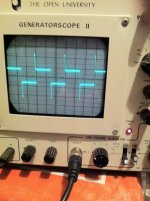
The square ware on the scope is perfect and so does the sine wave (measured at 1, 10 and 100Khz.
The sound is something out of this world ( with his home made speakers) the mids/highs are just fantastic with a nice controlled bass.
Congratulations for this FANTASTIC build and happy listening.
Ric
The only thing I can say is FANTASTIC
The build quality is FANTASTIC and for a FIRST build I don't know what to say apart from FANTASTIC.
We set the idle current to 350mA ( 1 channel was at 230mA and the second one at 330mA) and most confess that I got a bit confused with the manuals but I'm sure someone is going to help/correct me.
With the idle current set to 350mA how much current is flowing across the mosfets ?
The output offset was/is at 150mV because it could not be set in one channel so Rich decided to keep it at 150mV in both channels.
The square ware on the scope is perfect and so does the sine wave (measured at 1, 10 and 100Khz.
The sound is something out of this world ( with his home made speakers) the mids/highs are just fantastic with a nice controlled bass.
Congratulations for this FANTASTIC build and happy listening.
Ric
Thanks Ric,
I learned a little bit more about this black art ....
I can thank you enough for giving up your valuable family time to give my amp a check over with the scope ...
There was quite a bit of guess and hope for the best with this first build .
Thanks again , Rich
I learned a little bit more about this black art ....
I can thank you enough for giving up your valuable family time to give my amp a check over with the scope ...
There was quite a bit of guess and hope for the best with this first build .
Thanks again , Rich
Attachments
Had a good look at Rich's amp today... (in person in his flat)
The only thing I can say is FANTASTIC
The build quality is FANTASTIC and for a FIRST build I don't know what to say apart from FANTASTIC.
We set the idle current to 350mA ( 1 channel was at 230mA and the second one at 330mA) and most confess that I got a bit confused with the manuals but I'm sure someone is going to help/correct me.
With the idle current set to 350mA how much current is flowing across the mosfets ?
The output offset was/is at 150mV because it could not be set in one channel so Rich decided to keep it at 150mV in both channels.
The square ware on the scope is perfect and so does the sine wave (measured at 1, 10 and 100Khz.
The sound is something out of this world ( with his home made speakers) the mids/highs are just fantastic with a nice controlled bass.
Congratulations for this FANTASTIC build and happy listening.
Ric
How did you measure the idle current?
If I'm not mistaken, the A30 uses .47 ohm source resistors so the voltage drop across each one should be around 300mv for 600ma of current through each mosfet.
150mv of offset is much too high, there is a problem somewhere.
Sorry my bad, 350mV cross the .47 ohm resistor.
In the channel that could not be regulated down the problem looks to be the trimpot (the resistor (R106 in the schematic) was replaced by a trimpot ) wrongly wired to the board but since it was glued to the small strip of plastic with epoxy and we didn't have another to replace it we left it like that until Rich can get a replacement.
The trimpot would set the output offset higher but would not under 150mV and that is how I came to the conclusion the it was wrongly wired or am I wrong ?
Ric
Last edited:
I imagine you mean R11 on the A30 schematic. I can't imagine how it could do anything if it was wrongly wired. I suspect the matched front end fets were mixed up with the one for the CCS, or the trimpot was placed where R14 should be, and that won't work.
Hi Bill,
as per your advice , R8 was replaced with a 500R set @ 220R and R13 was replaced with 100kR set @ 47.5kR .... centre pins were soldered to side pins
Have I misunderstood something ?
Rich
as per your advice , R8 was replaced with a 500R set @ 220R and R13 was replaced with 100kR set @ 47.5kR .... centre pins were soldered to side pins
Have I misunderstood something ?
Rich
Last edited:
Hi Rich,
No, you have it right. Something else is amiss if it will not balance to zero. Check the voltage drops across all your source resistors and write it down, and check the voltage drop across R7, it should be somewhere around 4 volts and you should be able to adjust it up and down with R8. If you CAN adjust it up and down then there is a problem in the output section. I would then recheck all the resistor values.
No, you have it right. Something else is amiss if it will not balance to zero. Check the voltage drops across all your source resistors and write it down, and check the voltage drop across R7, it should be somewhere around 4 volts and you should be able to adjust it up and down with R8. If you CAN adjust it up and down then there is a problem in the output section. I would then recheck all the resistor values.
Unfortunately I live almost a 2 hours drive away from Rich...
We/I only measured the idle current and offset voltage (this one could not be set ) but the amp is working great with a perfect square wave at the output.
Nothing is overheating and with the idle at 350mV we can keep the hands on the heatsinks for as long we want.
I'm starting to wonder the lack of comments on the spike in the square in the picture posted.
Does someone know what was the cause ?
Ric
the spike could be from the source, or from a poor cable match, or from an improperly compensated probe, or ?
Did you compare an input square wave to output square wave?
Did you compare an input square wave to output square wave?
Gents ,
I checked the original 500r trimmer that . I works fine..... WTF . Should I put it back ?
Pass Mad Rich 😀
I checked the original 500r trimmer that . I works fine..... WTF . Should I put it back ?
Pass Mad Rich 😀
Cheers Ric , Andy ,
I have bias set as close to 0 VDC as possible , the idle set @ 350 ish VDC.
I want another project !
Rich
I have bias set as close to 0 VDC as possible , the idle set @ 350 ish VDC.
I want another project !
Rich
Cheers Ric , Andy ,
I have bias set as close to 0 VDC as possible , the idle set @ 350 ish VDC.
I want another project !
Rich
I keep thinking of a Burning Amp 2 with cascoded front end and higher rails......but not until the F-5X of EVULs is done, come on over to that thread!
Russellc
- Status
- Not open for further replies.
- Home
- Amplifiers
- Pass Labs
- Complete Novice Needs Help