Hans, don't worry about distortion, it is far bellow 0.016% , the lowest OS I made with ultra op amps. Take care about the second pole, look at mine , with bf199 I reach 80Mhz. The higher it is, more NFB can be applied. There are some new PNP rf transistors to try out for the Darlingtons.

Hans, don't worry about distortion, it is far bellow 0.016% , the lowest OS I made with ultra op amps. Take care about the second pole, look at mine , with bf199 I reach 80Mhz. The higher it is, more NFB can be applied. There are some new PNP rf transistors to try out for the Darlingtons.
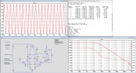
O.k. here you are, now with the BF199.
Distortion at 10Khz at +/-30 Volt with +/-3 uA input in 1Meg out is now 0.0016% and second pole is beyond 100Mhz.
You still owe me an answer why the dominant cap C2 should be that low in your situation and why you have such (over the top) requirements for a VAS.
With a ideal 5mA/V (Fet ?) input stage that you specified and an ideal OPS, both with a FR to infinity, your Amp would have GBW of 70Mhz without the need for a Cdom, a bit high to my taste for an Audio Amp.
But since both the non ideal IPS and OPS will add their phase, you will definitely need a Cdom that will drastically change the current gain at 10kHz.
For me it was just an intellectual challenge, confirming that this topology can be stretched to whatever needs, so here ends the road for me.
Hans
Attachments
For now you are working in single pole at 20khz. Later you will pass to two poles, the dominant pole can fall down to few khz. With mine 50khz 2 poles , the dominant is about 6khz. The problem in this design to have the distortion at 10khz adjusted with least feedback as later it will be in 2 poles where the 10khz is out of feedback.
You are right when you say the OS pole is the most important that limits the NFB, but if you followed my thread on 2 way feedback, you see that it can be eliminated , leaving the VAS and the IPS second poles to deal with. I am working on another type of feedback that eliminates all the second poles.
It is also to notice that it is your choice to over do, Is it really necessary to go differential ? If so, something extra it must provide.
Hayk
Last edited:
Some like you prefer push pull and some like me prefer balanced, although it is very well possible to make the Vas non balanced.For now you are working in single pole at 20khz. Later you will pass to two poles, the dominant pole can fall down to few khz. With mine 50khz 2 poles , the dominant is about 6khz. The problem in this design to have the distortion at 10khz adjusted with least feedback as later it will be in 2 poles where the 10khz is out of feedback.
You are right when you say the OS pole is the most important that limits the NFB, but if you followed my thread on 2 way feedback, you see that it can be eliminated , leaving the VAS and the IPS second poles to deal with. I am working on another type of feedback that eliminates all the second poles.
It is also to notice that it is your choice to over do, Is it really necessary to go differential ? If so, something extra it must provide.
Hayk
With a balanced Vas you can use a straightforward single long tail pair IPS while a push pull Vas asks for double the IPS complexity.
And the Vas that I proposed can easily be changed into a push pull Vas, thereby even eliminating the Wilson current mirror.
But I simply do not see the advantage of possibly getting a much larger slew rate in the hundreds of V/usec with a push pull symmetric-class AB IPS.
I prefer to keep it no more complex as needed.
I’ll wait and see how your final circuit will look like.
Succes,
Hans
I just finished a circuit that rejects feedback above 1Mhz, but gets it's stability by adding a LCR notch in front of the VAS. As it is no more 2 way feedback but re tailored VAS, I will return back to this thread tomorrow.
1. All your circuits are single ended in and out. Some people call a folded cascode a single stage but that is just semantics. But the point is that the connection between the IPS and VAS is not a given and the two have to work together, parts of one design.
2. You have a lot of bases with no "off" current source.
3. Speed is always paramount over linearity so the farther you go from a single transistor, the less likely a stable global feedback can be achieved. Being the dominant pole means you can hide some delay in the VAS but the principle still applies. Even a cascoded Darlington is pushing stability; the compensation cap around it can be an unstable local feedback loop.
This is a revolution

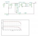
The feedback is limited to 1Mhz by inductor L1. The IPS modeled can be a single transistor of beta 500, working in CFA mode of 30mS , fixed by R1.
The LCR is not a real notch. The R7 must be equal to R1. L3,R7 is the same frequency as L1,R2 , 1Mhz. R7,C3 is about 100khz.The pole is at 6khz fixed by C2,R4.
With this configuration, the amplifier goes to open loop starting from 1Mhz. Finish ,all the stability stories and its margins. Now a new era starts where the HF character is truncated from the audio , finally.
Now, I must integrate the notch into the 2 pole VAS.
Attachments
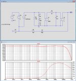
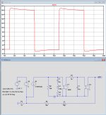
E1=-2000
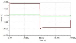
O.k. That's a lot better, see image below for the square wave.
Now up to the realisation with real components.
Hans
Attachments
Seeing the use of inductors here reminds me that one was used instead of a resistor in one arm the Quad 405 bridge circuit where the impact of this was offset by including a capacitor in another.
The feedback is limited to 1Mhz by inductor L1. The IPS modeled can be a single transistor of beta 500, working in CFA mode of 30mS , fixed by R1.
The LCR is not a real notch. The R7 must be equal to R1. L3,R7 is the same frequency as L1,R2 , 1Mhz. R7,C3 is about 100khz.The pole is at 6khz fixed by C2,R4.
With this configuration, the amplifier goes to open loop starting from 1Mhz. Finish ,all the stability stories and its margins. Now a new era starts where the HF character is truncated from the audio , finally.
Now, I must integrate the notch into the 2 pole VAS.
Hayk,
I'm still anxiously waiting for the realisation of your closed-loop/open-loop high BW concept.
Hans
What is the present state of this research? What is the best circuit for a Vas and cascode stage when I want to built an amplifier with no global feedback? I mean the lowest distortion and an open loop BW above 20 kHz.
The 10pf here defines the dominant pole, can be from the output or both for double pole.
It is Wilson with Darlington . Simple but never seen.
I don't think that there some circuit never seen, look this, similar Wilson with super pair (Boxal).😀
No NFB line amp (GainWire mk2)
I love cascode VAS stages, but I gave up driving the base of the VAS stage a long time ago (20 years). Now I drive the emitter (or source, if it's MOS) of the cascode transistor directly from the diff-amp output. I get a much higher GBW product.
- Home
- Amplifiers
- Solid State
- Comparative VAS+cascode stage