Hi Hayk,
Can you share your 0.016% OPS?
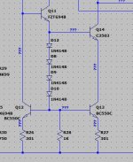
Regarding LKA's circuit, is it the one in the attached picture?
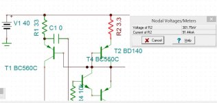
I missed one wire. See the attached circuit... I drew it at 2am hence why I messed up the circuit and your name... sorry about that.Your proposed circuit is not operational
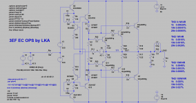
The best output stage I have is 0.016% 60w 10khz. LKA proposed excellent triple cascade emitter followers , may be best state of art ,has 3.5% Dtot
Can you share your 0.016% OPS?
Regarding LKA's circuit, is it the one in the attached picture?
Attachments


Hi LKA, can you share a .asc? Thanks!
BTW, you avatar picture looks like a 1984 Sardaukar from Dune.
BTW, you avatar picture looks like a 1984 Sardaukar from Dune.
It is me ... welding helmet 🙂
Thanks! What does LKA stand for?
See attached photo: Sardaukar vs. LKA
Attachments

The FZT can be replaced? I don't have spice model. This mirror has current gain of 1 I suppose. The collector of FZT is grounded?
Last edited:
Yes, it maybe replaced. The ratio is 1:1 due it's load of VAS stage. Just only take a picture from my amp.
Change it to 10:1 as you want.
Regards,
Cuong Nguyen
// Collector of FZT be connect to GND or V+ rails. In my design, its connected to V+rail because i want design look as op-amp, not ref. with GND.
This thing cause FZT will dissipate more heat.
Change it to 10:1 as you want.
Regards,
Cuong Nguyen
// Collector of FZT be connect to GND or V+ rails. In my design, its connected to V+rail because i want design look as op-amp, not ref. with GND.
This thing cause FZT will dissipate more heat.
Last edited:
Main reason i use FZT because its high Hfe single transistor. It reduce offset of current mirror. Some other descriptions use MOSFET due its advantage that Gate current near as zero.
So, the solution i have are:
1. Use high Hfe devices, beta enhanced config etc...
2. Small signal MOSFET
Regards,
Cuong Nguyen
So, the solution i have are:
1. Use high Hfe devices, beta enhanced config etc...
2. Small signal MOSFET
Regards,
Cuong Nguyen
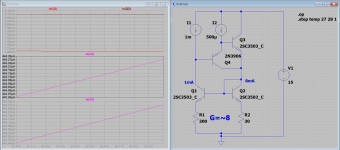
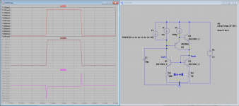
Your circuit is still un operational.
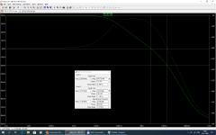
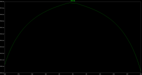
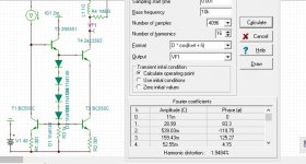
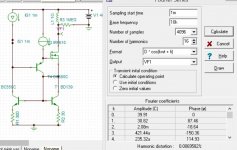
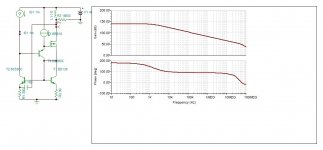
The circuit is quite operational, see below. Give it a go with your setup and models, let's see what it gives. I don't want to do it on my end due to different simulator/models/settings/etc.
Also, it does need some compensation to keep it stable, see the second plot.
Attachments
Last edited:
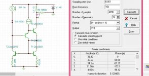
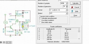
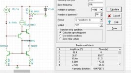
Using adequate transistors the distortion is halved .With IS1 1ma it becomes 0.059%. With 50v supply it is 0.039%.
Attachments
Last edited:
Looks good... not bad for just 4 transistors.
I am amazed the MOSFET got us 10x distortion reduction.
In the BJT version, T4 corrects base current error due to Early Voltage, and errors due to CJC.
In MOSFET version, T4 only corrects for CJD.
This means that the base current error is quite dominant given we got that 10x reduction.
Here is a test, what happens if we repeat the test with the circuit in #35 using a PNP (T4) with higher Beta (increase the model beta by 10x).
My theory is that distortion should go down substantially... tbd.
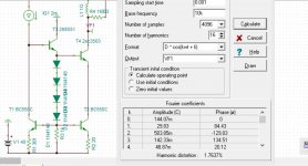
I passed the beta from 845 to 8450 the distortion fell from 0.06% to 0.04%.
The circuit on 27 is only two transistors with lower distortion but lower second pole .
The circuit on 27 is only two transistors with lower distortion but lower second pole .
Last edited:
I am trying out different types of VAS+cascode stage for lowest distortion. These are the ones I tested. Please ,suggest other ones I try out.
The stage must provide a current gain of 10, to bring the 1M ohm load to +/-30v 10khz.
The first circuit has anomolously high distortion, yet its output swing isn't excessive, so I suspect the cascode device base voltage is too low - the current through R2 is stealing from the available voltage. Try making the voltage bias for the cascode 2V or 2.5V maybe?
Perhaps change R2 to 100 ohms also, it would normally be pretty small if present.
- Home
- Amplifiers
- Solid State
- Comparative VAS+cascode stage