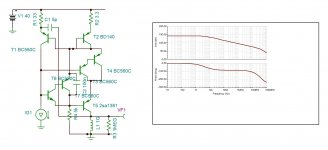
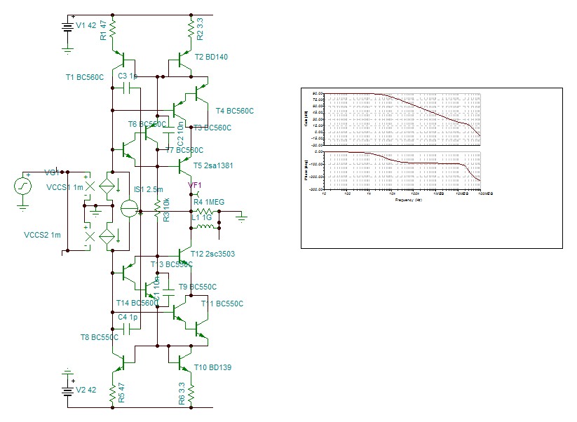
I am trying out different types of VAS+cascode stage for lowest distortion. These are the ones I tested. Please ,suggest other ones I try out.
The stage must provide a current gain of 10, to bring the 1M ohm load to +/-30v 10khz.
The stage must provide a current gain of 10, to bring the 1M ohm load to +/-30v 10khz.
Attachments
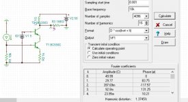
The output stage is the emitter follower, The VAS must convert the current of the input stage into voltage . The cascode highers the impedance of the VAS by decreasing the Early character, hence more trans resistance with less distortion. It is the most common solution applied in high performance amplifiers , I don't know if there is another way.
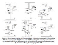
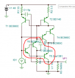
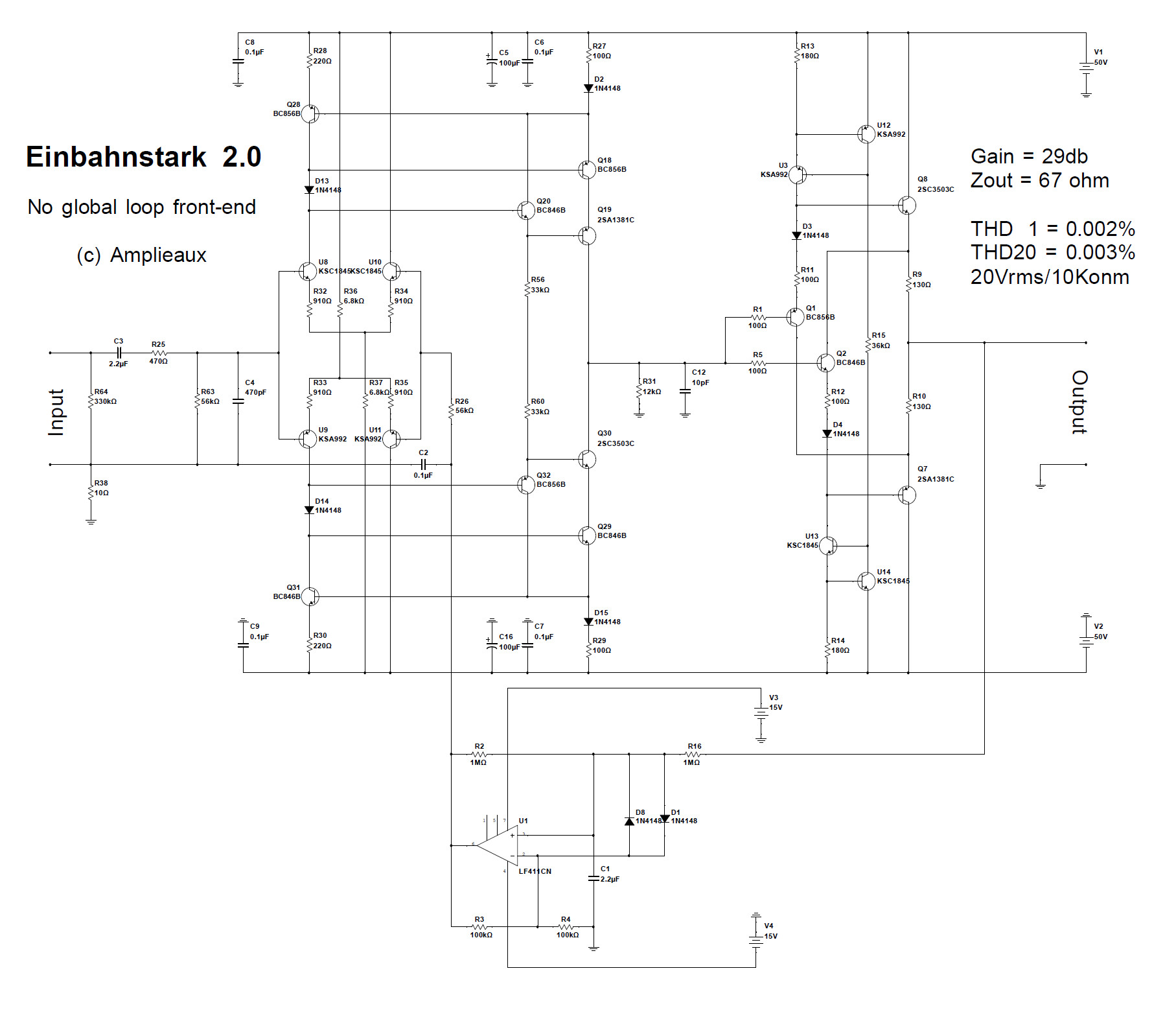
Hi Hayt, let me use a picture rather than words. What is the logic for your decision to optimize circuit (d) in the attached picture vs. circuit (c)?
I am not challenging you here, I am asking a very simple question, since you could have chosen to optimize circuit (c).
"The cascode highers the impedance of the VAS by decreasing the Early character, hence more trans resistance with less distortion."
This is only true below the dominant pole, assuming strict Miller compensation or Transitional Miller Compensation.
"It is the most common solution applied in high performance amplifiers , I don't know if there is another way."
See circuit (c) in the attached picture. That is what the Honey Badger, the BC-1 from Bob Cordell and most of Doug Self's amp's use. I think that is the most common solution in high performance amplifiers.
Attachments
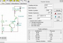
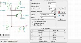
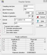
Strangely , with gain of 15 ,I get the lowest distortion of 0.002%. In push pull it may cancel the even orders to decrease further the distortion.
Hayk
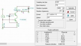
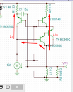
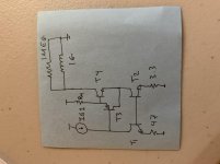
This looks like an augmented PNP wilson current mirror to me with a current gain of R1/R2 = 47/3.3 = ~14.2
Attachments
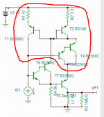
Hmmm... yes the distortion will go hell. The culprit is the CJC of T3. As you move Vout, CJC_T3 injects a current to the input of the mirror, which gains it up by ~14x to the output. So you get 15 units of distorted current at the output. I just reminded myself why current mirrors are awful as gain stages.
Sorry for the crappy suggestion.
Sorry for the crappy suggestion.
Attachments
Last edited:
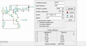
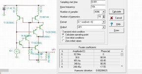
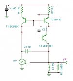
This is the push pull version with millers 1pf to the input. The distortion is 0.0005%. Of course it is useless as the output stage has far higher distortion.
The topology is nothing new. If the Darlingtons are reduced you get Vzaichenko's VAS + cascode
The topology is nothing new. If the Darlingtons are reduced you get Vzaichenko's VAS + cascode
Attachments
Last edited:
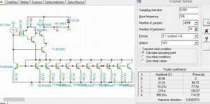
Your proposed circuit is not operational. Even linking the base to collector of the input mirror, the pair output doesn't transfer any current.
I tried simple mirror ×10 with cascode, the distortion is 1%.
I will aim in 0.01% region tomorrow but simpler topologies with MOSFET VAS + bjt cascode. The best output stage I have is 0.016% 60w 10khz. LKA proposed excellent triple cascade emitter followers , may be best state of art ,has 3.5% Dtot . So, bellow 0.01% for VAS is useless.
Hayk not Hayt , before it was written as Haïk, but with internet era , the Armenians changed it I never new why.
Attachments
Last edited:
- Status
- This old topic is closed. If you want to reopen this topic, contact a moderator using the "Report Post" button.
- Home
- Amplifiers
- Solid State
- Comparative VAS+cascode stage