
The inductance of a 30" twisted pair cable will be about 20 nH. Forget about the inductance of the connecting wires for such short lengths. Most likely, the whole catch is in the output filter of the amplifier. As soon as the speaker impedance decreases in relation to the low-pass filter setting in the amplifier, the effect will immediately appear the inductance of the output low-pass filter amplifier in the form of additional inductance, and this inductance can be from 20 μH to 40 μH, it depends on the manufacturer of the amplifier.The amplifier makes you a roll-off in the frequency response, since the output low-pass filter of the amplifier is not covered by feedback.There is probably about 30" of twisted pair wire between the amp and the tweeter... Surely twisted pair wire would not add this much inductance? or maybe yes?
If the parts are accessible it is a simple way to try and count one problem out before considering more obscure reasons. There may be an unexpected interaction in the passive parts, a simple electronic frequency response will tell you if the problem is there or somewhere else.I agree that is a concern in any analog circuit. In this particular case, I can not simulate this response with any reasonable variation in the tweeter crossover values.
Can you show the impedance plots as well for both cases, sim and real?
Another thought, you could measure the filter itself with LIMP , as well as the individual components.
And then relocate the components like @chargedcapacitor suggests to see if it results in measuable difference, as the diff you noticed is pretty significant therefore must be measurable.
Very interesting, as i am shortly going the redesign my filter myself, and the laborious part is the measurement of components and assembled filters, yet very revealing regarding behaviour of notably capacitors and inductors over the audio frequency range.
I once tried to simulate a capacitor with 4.5 meter speaker wire by arranging it "capacitor-like" and running test signal through a speaker and measuring with a mic. There was no measured difference and the FR-lines were complete overlaps from top to bottom. I repeated the same test with speaker wire arranged as a coil, but with exactly same results. So I doubt that wire would be the cause. I now have an inductance and capacitance tester, I probably should rerun the wire geometry test.
I see you use a chipamp, they are known to have load dependency for highs. That's my best guess like others above.
I see you use a chipamp, they are known to have load dependency for highs. That's my best guess like others above.
Oh wow I'm in love! 😍 😉Yes, it controls the 5" midwoofer breakup. In this particular case, I can change the notch filter values by +/- 10% without affecting the response too much.
I measured the woofer response with the crossover, and it agrees closely with the sim. When I measured the tweeter response with the crossover, I see the difference... a rolloff starting at about 7k and growing to be about 3 dB at 16k.
Good thought...The wiring length definitely changed. For the testing of the drivers, I was using short leads from the amp to the drivers. The actual finished system uses longer wiring. As you can see, I used twisted pair wiring for a neater installation. There is probably about 30" of twisted pair wire between the amp and the tweeter... Surely twisted pair wire would not add this much inductance? or maybe yes?
View attachment 1261099
yes that is correct.
I agree that is a concern in any analog circuit. In this particular case, I can not simulate this response with any reasonable variation in the tweeter crossover values.
Interesting... I need to think on that. I need to think about how the inductors were arranged in the cabinet.
Thank you for all the comments...... j.
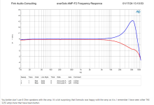
K.H.Fink posted in ASR his measurement of a recent class-D amp, showing the FR deviation.
Post #14:
https://www.audiosciencereview.com/...f2-class-d-power-amplifier-coming-soon.47651/
Post #14:
https://www.audiosciencereview.com/...f2-class-d-power-amplifier-coming-soon.47651/
Attachments
Can you show the impedance plots as well for both cases, sim and real?
Dashed curve is the measured impedance of the mid+tweeter+crossover. Solid curve is the simulation
Now here is the same plot with 0.039 mH of parasitic inductance added to the tweeter ciruit
It seems that if there was actually this parasitic inductance between the amp and the tweeter filter, it should show up as a rising impedance above 7k... and the actual measured response does not show that.
I have confirmed that the high frequency rolloff is the same in both speakers, it is stable, and it is not voltage dependent. I get the same result at 60 dB SPL and at 95 dB SPL.
When I tested the crossovers before installation, they were physically arranged in a very different way than they are now in the cabinet, yet I measured the same high frequency rolloff.
The theory from @uriy-ch seems to best match the facts at this point.
If the parts are accessible it is a simple way to try and count one problem out before considering more obscure reasons. There may be an unexpected interaction in the passive parts, a simple electronic frequency response will tell you if the problem is there or somewhere else.
I am reluctant to remove the woofer to get access to the crossover. I think an easier test would be to make a frequency response plot of the amp with the driver+filter load connected. This would confirm or refute the idea that the amplifier has a load-dependent frequency response.
However, I need to get a spare XLR or TRS cable and figure out how to splice/hack it into the output of the amp.
Again, thanks for all the excellent ideas and comments. Progress is a team sport... thanks team !
j.
Jim, have you measured with and without DSP in place, just to make sure the DSP isn't failing, or the mic preamp isn't failing, or the mic got damaged, etc? Something may have changed in your playback or recording setup.
@augerpro - to the best of my capabilities, I have made certain that nothing in the playback or instrumentation setup is out of whack.
I substituted other speakers as the unit under test, and confirmed I get the same frequency response from those speaker as I have measured in the past.
In post 613, the measured response curve was taken with no DSP in the loop... my ARTA setup was fed directly into the amp.
j.
I substituted other speakers as the unit under test, and confirmed I get the same frequency response from those speaker as I have measured in the past.
In post 613, the measured response curve was taken with no DSP in the loop... my ARTA setup was fed directly into the amp.
j.
I have made a frequency response plot of the amplifier output, with the mid+tweeter+crossover as the load.
The plot is in dB, but please be aware that is a relative dB. In other words, 0 dB is not referenced to anything in particular. The actual measurements were made at an amplifier output of about 1 Vrms.
This data confirms that the amplifier frequency response is not flat when connected to this loudspeaker load. There is a peaking of about 0.5 dB at 4k, and then a drop of more than -2 dB at 20k. This matches closely with the acoustical measurements in post 613 https://www.diyaudio.com/community/threads/compact-low-cost-active-3-way-speaker.402812/post-7570120
Thanks to those who pointed out the possibility that this inexpensive class D amp might have a sensitivity to output load impedance. @uriy-ch , @IamJF , @Draki , @JukkaM - - Thanks !

Now that I know the source of the anomaly, I am more comfortable in simply compensating it in the DSP filter.
j.
The plot is in dB, but please be aware that is a relative dB. In other words, 0 dB is not referenced to anything in particular. The actual measurements were made at an amplifier output of about 1 Vrms.
This data confirms that the amplifier frequency response is not flat when connected to this loudspeaker load. There is a peaking of about 0.5 dB at 4k, and then a drop of more than -2 dB at 20k. This matches closely with the acoustical measurements in post 613 https://www.diyaudio.com/community/threads/compact-low-cost-active-3-way-speaker.402812/post-7570120
Thanks to those who pointed out the possibility that this inexpensive class D amp might have a sensitivity to output load impedance. @uriy-ch , @IamJF , @Draki , @JukkaM - - Thanks !
Now that I know the source of the anomaly, I am more comfortable in simply compensating it in the DSP filter.
j.
In class D amplifiers, a low-pass filter (LPF) is placed at their output for demodulating the Pulse Width Modulation (PWM) signal. If this LPF is not covered by feedback, there will always be an influence of the LPF properties between the amplifier and the load. It is this LPF that possesses such physical properties; it is capable of altering the amplitude of the output signal when the load resistance changes. In post number 627, this property is precisely depicted in the lower picture; please study the images attentively. In class D amplifiers where the LPF is covered by feedback, such an effect is not observed because the feedback monitors the LPF output signal and makes necessary corrections to prevent such changes in the LPF output signal at the load.For us non-sparkies, can someone explain the conditions in which this could arise?
How would i reckognise such an amplifier? In other words would amps like hypex or purifi also have this frequency response behaviour?
In class D amplifiers, a low-pass filter (LPF) is placed at their output for demodulating the Pulse Width Modulation (PWM) signal. If this LPF is not covered by feedback, there will always be an influence of the LPF properties between the amplifier and the load. It is this LPF that possesses such physical properties; it is capable of altering the amplitude of the output signal when the load resistance changes. In post number 627, this property is precisely depicted in the lower picture; please study the images attentively. In class D amplifiers where the LPF is covered by feedback, such an effect is not observed because the feedback monitors the LPF output signal and makes necessary corrections to prevent such changes in the LPF output signal at the load.
I actually understood that! Thank you! So is this found only in cheap D-class amps?
- Home
- Loudspeakers
- Multi-Way
- Compact, low cost, active 3-way speaker