Hello,
I really want to go for the dual mono power supply.
The chassis I got are too small for two toroidal transformers 300VA in the same enclosure.
I`ve done some research:
1. http://www.modu.it/economicaep.html
It is cheaper for me to buy three of these enclosures than to buy one more (230x230mm ) gallaxy enclosure from the same company.
For this exact build I do think I like the looks of the economicae line better than the gallaxy line...
See attached digital drawings !
I guess there is no problem building two separate PSU enclosures for this build.... - any inputs?
Thanks!
Endre
Attachments
Last edited:
signal XLRs have the male as output and female as input.
Power when fed through XLRs usually reverse this, to female as output and male as input.
This prevents inadvertent mis-connection when using a standard male to female cable.
Think about how your 4pin power sockets could be mis-connected. You may have no problem if you have no other 4pin sockets.
Power when fed through XLRs usually reverse this, to female as output and male as input.
This prevents inadvertent mis-connection when using a standard male to female cable.
Think about how your 4pin power sockets could be mis-connected. You may have no problem if you have no other 4pin sockets.
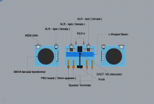
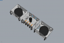
Great pics Endre! Two things came to my mind when looking at your pictures and thinking about my own goal to build two monoblocks. But I still did not order any parts so I can still change my mind...
1) What is your main consideration to separate the PSU from the amp housing? Do you want to shield / separate the mains hash and high voltage influences from the amp?
2) It looks like you put the amp boards vertically with the chips on the bottom plate. Then what do you use the L-shaped profile for? To support the attenuator axle + the capacitors?
3) Will the economic housing distribute the heat well enough? Probably will because it is a large surface connected to other panels at the back and sides.
Yes indeed the Mundorf terminals look really swell at the front and easy to tighten with the wings!
Have fun
Regards, Frederick Joan
Signal XLRs have the male as output and female as input.
Power when fed through XLRs usually reverse this, to female as output and male as input.
I did not know this. Thank you for explaining! Will adjust this to:
Output PS Enclosure = female output.
Input LM3875 Amp = male input.
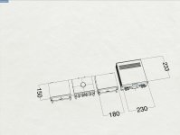
1. I want this amplifer of mine to look "clean" - I guess separating the different parts will give a simpler layout. I also found out that it was too crowdy putting two 300VA transformers within one galaxy (230x230mm) enclosure. Therefore thinking three economy chassis instead.
2. In the first place I`m using the L-shaped profile to support the attenuator. I guess by making an extension to both sides I have a place to also install the caps on the two main boards too - like Peter did in his manual.
3. I sure hope so....
Regards,
Endre
Can you buy ready made 4pin XLR cable?
Blue Jeans is a good source, I bought many 10m 3pin XLR mic cable from them.
Blue Jeans is a good source, I bought many 10m 3pin XLR mic cable from them.
If I could just order the standard version of the Trichord Research Dino power supply lead ( or similar ) I will not buy the expensive one.
It has a 4 pin xlr ( both female and male ) .....
It has a 4 pin xlr ( both female and male ) .....
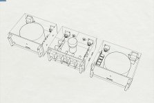
Hi !
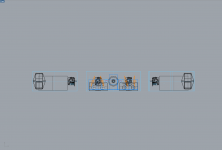
now... I have finally landed on a chassis design I think will work really well.
For me ... I just wanted to share this setup.
The chassis I´ve used for my drawings are really cheap compared to other chassis designs out there. Same manufacurer as last time.
The three chassis used for this setup are really small.
All three are 180mm in width and 150mm in depth and 80mm in height.
Thats roughly: 7 inches x 6 inches x 3 inches.
Small enclosures was something I found important in drawing these last enclosures. Before I thought the chassis I had were small... See comparison and you`ll see there is quite a big difference...
Regards,
Endre
Attachments

Nice work Endre!
That is going to be a slick amp package. Now you just need to build it and post some pictures of it!!!
I like the idea of having the volume control on the top of the unit - it's something I am contemplating also!
Cheers,
Tim
That is going to be a slick amp package. Now you just need to build it and post some pictures of it!!!
I like the idea of having the volume control on the top of the unit - it's something I am contemplating also!
Cheers,
Tim
hello !
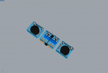
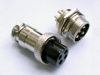
I have a question regarding the connectors for my umbilical chord.
I´ve found this type of connectors. ----- see attached photo.
These are units used in other designs for power supply.
Will this type of connectors work well for the umbilical chord for the LM3875 kit too?
I have a question regarding the connectors for my umbilical chord.
I´ve found this type of connectors. ----- see attached photo.
These are units used in other designs for power supply.
Will this type of connectors work well for the umbilical chord for the LM3875 kit too?
Attachments
That's the same connector I've been using in AMP-1: 6moons audio reviews: Audio Zone AMP-1 by Audio Oasis
Hi everyone,
Could any one help me with some advice on internal wires for my Gainclone? What would be the difference between Cardas, Kimber or any other popular brand? I read some positive comments on Kimber, which are still affordable too.
How would the character of the sound compare to for example Cardas? I am looking for a natural, non spectacular sound which does not distract from the music. Considering the character of the GainClone sound which is generally considered as a bit on the analytical / clinical side maybe a tad warmth and slight rolling off of the higher frequencies would not hurt. I also intend to use full range speakers in the future with some emphasis of the mid to high frequencies as well (think horn loaded Fostex speakers). Another reason for needing unobstrusive internal wires, interconnects and loudspeaker cables.
Secondly, what about the hype around expensive mains cables and plugs? Are they worthwhile or should I stick to relatively simple shielded mains cable with low budget but robust plugs?
Thirdly, I am considering a trick to delete the RCA connectors alltogether. What about soldering the interlink directly to the PCB? Of course I would need some kind of train relief to prevent unwanted mechanical loads on the solder connection. This would be the best for sound quality wouldn't it? Since my amp will only have one input. I do not expect to change the interlink so why not making it part of the amp? Same with mains cable.
Any wiring suggestions for my gainclone build would be most welcome.
Regards, Frederick Joan
Twisted pairs/triplets everywhere.
Some low level signal wiring might benefit from star quad wiring.
A few commercial audio offerings had fixed signal output wiring.
Saved the cost of phonos and the soldered joints at the phonos.
There is lots of anecdotal comment that soldered In/Outs are better than some/all connectors.
Some low level signal wiring might benefit from star quad wiring.
A few commercial audio offerings had fixed signal output wiring.
Saved the cost of phonos and the soldered joints at the phonos.
There is lots of anecdotal comment that soldered In/Outs are better than some/all connectors.
Last edited:
I am looking for a natural, non spectacular sound which does not distract from the music. Considering the character of the GainClone sound which is generally considered as a bit on the analytical / clinical side maybe a tad warmth and slight rolling off of the higher frequencies would not hurt.
That's exactly how Cardas sounds, however, if you only use few inches of the cable, inside the amp, going with Cardas might not be practical, as solder pot is needed to tin the leads.
Kimber is fine too, I don't really remember now how it sounded, my only recollection is that it was less "spectacular" than Cardas inside 2ft umblilical cord between the amp and external PS.
The hype around power cords is true, however I never really bothered much with cords on Gainclone, I'm just using 14ga regular cords and it's fine with me. However, I will certainly not recommend any mains filtering. Same for exotic fuses, I tried them on few occasions, but never noticed much difference in real life performance.
I also went through the phase of removing RCAs and soldering cables directly, but presently wouldn't bother with that: it's not practical and gains are not worth it, unless one is trying to safe some money.
In that case you may consider terminal blocks of that type: Extending Terminal Blocks - Protostack The spacing of pads on pcb should be compatible with some of them.
Some additional info on wire was posted here as well: http://www.diyaudio.com/forums/audi...-kit-building-instructions-2.html#post1514854
Thanks for reply Peter and AndrewT.
One question about triple and quad wire for interlinks like Kimber has. Normally a one channel interlink has only two leads plus maybe shielding. How to connect the third and/or fourth wire? Sorry I do not understand how to connect them.
Frederick Joan
One question about triple and quad wire for interlinks like Kimber has. Normally a one channel interlink has only two leads plus maybe shielding. How to connect the third and/or fourth wire? Sorry I do not understand how to connect them.
Frederick Joan
A Circuit has a Flow from the Source voltage and a Return to the Source voltage.
A Circuit MUST have TWO wires.
A Third wire is not required to allow a circuit to work.
Forget about the generalised word "ground".
Think about circuits and the ROUTE that the current must take to get from the Source and BACK to the Source.
A Circuit MUST have TWO wires.
A Third wire is not required to allow a circuit to work.
Forget about the generalised word "ground".
Think about circuits and the ROUTE that the current must take to get from the Source and BACK to the Source.
Hey AndrewT, thanks for your suggestion about better understanding of circuits. Well then, I guess part of the circuit could consist of two wires in parallel, which was called Ground by Peter. He probably means that these two parallel wires will be connecting the outer parts of the RCA connector?
Reg, Frederick Joan
Reg, Frederick Joan
But why would Kimber do this? What is the point in having two wires for the return and only one wire for the signal? Has it got anything to do with shielding and the way they braid the wires?
Regards, Frederick Joan
Regards, Frederick Joan
- Home
- More Vendors...
- Audio Sector
- Commercial Gainclone kit- building instructions