Audiosector basic mono block amps
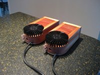
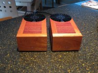
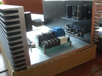
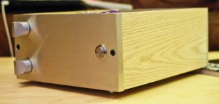
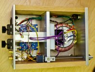
Here's my version of the basic mono blocks. 22v-300va toroidals... have put about 100 hrs on them with 8ohm speakers. I will be using them on a pair of PSB Alpha b1s most of the time.
Here's my version of the basic mono blocks. 22v-300va toroidals... have put about 100 hrs on them with 8ohm speakers. I will be using them on a pair of PSB Alpha b1s most of the time.
Attachments
Here's my version of the basic mono blocks. 22v-300va toroidals... have put about 100 hrs on them with 8ohm speakers. I will be using them on a pair of PSB Alpha b1s most of the time.
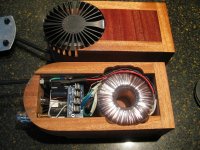
Great build! Love the look. What heat sinks are those?
The heat sinks are from a company called Lamina.Great build! Love the look. What heat sinks are those?
http://products.lsgc.com/uploads/tx_flexproducts/Light_Engine_5-21-08_Accessories_Datasheet.pdf
I got them from Mouser. like 25 bucks a piece.
erpii, nice looking and very original design 
There is nothing really particular about bi-amping, just split the signal and connect to both amps.
You may try using smaller filter caps in mid-highs amp, especially BG N 100/50 work great here, if you can still find them.
I have a set of KEF Q5 speakers which support Biamping, i.e. seperate binding posts for HF/LF.
Have you got a guide/any advice for bi amping and would you use different components on the amp pcb for the high and low frequency channels?
There is nothing really particular about bi-amping, just split the signal and connect to both amps.
You may try using smaller filter caps in mid-highs amp, especially BG N 100/50 work great here, if you can still find them.
Last edited:
The R3 resistors in my kit seems to be 751 ohm, not 680 as mentioned in the building instructions. (violet, green, brown, brown). Is this the correct resistors, or have I mixed up something?
Rikens are discontinued and 680Rs not available any longer. I had stock of 620R and 750R Rikens which I was supplying as an alternative to 680R, but starting this year I'm switching to Kiwames, which basically are the same soundwise.
Rikens are discontinued and 680Rs not available any longer. I had stock of 620R and 750R Rikens which I was supplying as an alternative to 680R, but starting this year I'm switching to Kiwames, which basically are the same soundwise.
OK, sounds good then. So the 70ohm difference doesn't really affect the sound?
Regards
Erik
erpii, nice looking and very original design
There is nothing really particular about bi-amping, just split the signal and connect to both amps.
You may try using smaller filter caps in mid-highs amp, especially BG N 100/50 work great here, if you can still find them.
Ok thanks, i have a few questions:-
1. Do i just run 2 wires from each RCA input, one to Hf amp board and one to Lf amp board?
2. Would i benefit from using 4 transformers? 1 for each amp or would 2 be adequate?
3. would i have to use 2 pots? or is there another way?
thanks again
Dan
OK, sounds good then. So the 70ohm difference doesn't really affect the sound?
How can it affect the sound? It can only affect the gain, but it's so little that it's negligible 😉
1. Do i just run 2 wires from each RCA input, one to Hf amp board and one to Lf amp board?
2. Would i benefit from using 4 transformers? 1 for each amp or would 2 be adequate?
3. would i have to use 2 pots? or is there another way?
1. Yes
2. I wouldn't go wit 4 transformers: 2 is enough, especially when high pass channel has much lower power requirements.
3. One pot is enough, right after RCAs, and signal split after the pot.
No additional resistors are needed, as you already have series/shunt input resistor divider on amp board (220/22k)
It's best to change the gain with R3, but I wouldn't go over 1k6 or so. If you need additional gain trimming, increase R1 (22k will give you -6dB gain reduction)
It's best to change the gain with R3, but I wouldn't go over 1k6 or so. If you need additional gain trimming, increase R1 (22k will give you -6dB gain reduction)
I think you need to replace your chip.
I've just finished replacing the chip and insulating all the wires so it would happen again. However, the offset at the speaker posts is still way to high (34V). Anyone any thoughts about what could be the case here?
Greets,
Erik
What about other parts on the board.If it's not a problem try to desolder them and check.(I'm suspecting on one of capacitors,usually they fail first after the chip). On the rect boards also.
Regards
Regards
Grounding of brided LM4780
Hello Peter,
i just recieved my transformers for my amps. I use 4 of your lm4780 in bridged mode, 2 per channel, 1 for highs and 1 for lows with an active cross over. The transformers are 200VA each, and each LM4780 wil have its own transformer and rectifier board, so the amp will be completely dual mono.
xlr input--LM4780 bridged--rectifier--transformer.
Each transformer has 2 x 2x 24 and one central ground. As i understand i need to use a star ground for the PS and connect the signal gnd directly to the LM4780 board. But i still have some questions
- should i also connect the central earth of the transformer to the star ground?
- should each channel have its own star ground? (but i use a full aluminum casing
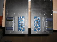
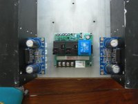
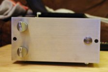
Some pictures of my housing, first setup. There will be a dual compartment in the front, for each transformer
I also added a soft start and a speaker dc protection (central pcb). The amps will have xlr inputs and get signal from an active cross over and pre amp (both fully balanced).
In the pictures you can also see the transformer i will be using (4 in total, 2 per amp), R-core 200VA
Finally i will use a copper bar to press the LM's to the heat sink and not use the screws like in the pictures.
regards,
Harold
Hello Peter,
i just recieved my transformers for my amps. I use 4 of your lm4780 in bridged mode, 2 per channel, 1 for highs and 1 for lows with an active cross over. The transformers are 200VA each, and each LM4780 wil have its own transformer and rectifier board, so the amp will be completely dual mono.
xlr input--LM4780 bridged--rectifier--transformer.
Each transformer has 2 x 2x 24 and one central ground. As i understand i need to use a star ground for the PS and connect the signal gnd directly to the LM4780 board. But i still have some questions
- should i also connect the central earth of the transformer to the star ground?
- should each channel have its own star ground? (but i use a full aluminum casing
Some pictures of my housing, first setup. There will be a dual compartment in the front, for each transformer
I also added a soft start and a speaker dc protection (central pcb). The amps will have xlr inputs and get signal from an active cross over and pre amp (both fully balanced).
In the pictures you can also see the transformer i will be using (4 in total, 2 per amp), R-core 200VA
Finally i will use a copper bar to press the LM's to the heat sink and not use the screws like in the pictures.
regards,
Harold
Attachments

My first diy amp
Finally I finished to assembly my first chip amp. Not totally true, The only thing missing is the cover. First I thought about perforated aluminum for the cover, but the amp seems to not produce much heat, I think simple aluminum sheet will do the job.
My amp is based on Peter designs and ideas. As the Blackgate N 100 are so expensive, I go with Blackgate K 100 ( it is FK but in more compact version). I just take the integrated version and made it more compact. Just test it with Philip Glass string quartet and it sound great. Now, I need to find a place to anodize the faceplate.
Attachments
etoiledusoir - nice looking amp! Have you shrunk the case dimensions and made your own or are you using parts bought from Peter?
Hello everyone!
I'm just starting to put together my first LM3875 kit! I'm very excited yet a bit worried since the most complicated thing I've built was the Millet Hybrid from the headfi.org world. I think I'm rightfully scared given that I haven't dealt with main line electricity before.
In any case I had four questions:
1) I live in the US and I'm trying to figure out how to safely ground the chassis and everything. I'm building a stereo with one rectifier and transformer. Can any more experienced DIYers in the US suggest what screw size and bolts and gauge wire I should be using to ground things to Safety Earth? Otherwise I was going to emulate P. Daniel's set up at the beginning of this thread to the best of my abilities.
2) I have some left over Blackgate NX 47uF 6.3V. Is there anyway I could use them on the rectifier bridge or is the voltage rating too low?
3) I wasn't sure how to gauge how hot the LM3875 chips would run. I was thinking of using these heatsinks: http://se.mouser.com/Search/Product...000Gvirtualkey53210000virtualkey532-569003B00 Would they be adequate or do I need something more hefty? I'm planning to use these to drive 8ohm speakers without a pot so I imagine they would run pretty hot.
4) Since I'm not using a pot, do I need to add some resistance there? I'm hoping to get as much power as I can since my speakers are relatively inefficient (86db). I'm guessing that I don't need to and that I can solder the RCA connections directly to the PCB, but I figured it wouldn't hurt to ask...
Thanks! and by the way, very impressed with the helpfulness throughout this thread I hope the kindness will extend to me as well =)
Last edited:
1. I use 14 gauge wire for safety ground crimped into a ring tongue terminal. The screw should be 8-32 or larger and a lockwasher should be used under the nut.
2. Capacitors should be rated 50 volts or more; the 6.3 volt capacitor cannot be used at the rectifier output.
3. If there was supposed to be a link to heatsink data it didn't show up. Use the largest heatsink you can fit in the chassis. Mine is 4"x7" with 2" fins. I see you added the heatsink link - it looks far too small. I am using a 4" section of the heatsink from Ebay item 250509769380. There is a picture in the auction.
4. Peter's amplifier circuit board has places for input resistors, R1 and R2. Additional resistors are not needed.
Last edited:
This amp will drive your 86db speakers to about 100db with cdp straight to the amp. Thats loud. Really loud.
- Home
- More Vendors...
- Audio Sector
- Commercial Gainclone kit- building instructions