Hi,
My question is; since there are no isolation between the metal chassis and the connector, I think I will get the same signal level ground on both connectors, and also a common connection to the grounding, right? This can't be good I guess?
Do I need to buy some new isolated connectors, or can I use these somehow?
You will need to isolate the connector from the chassis. If you can find fiber shoulder washers that fit the jacks, that will work. Otherwise buy better jacks - most people use gold plated jacks that come with insulating washers.
I have access to two 12-0-12 trafos, 4 amps each. I want to drive two 8 ohm speakers. Is htere away to use these trafos for this amp kit? And if yes, could you point me to the thread for the rectifier configuration?
In that case connect each trafo (secondaries in series) separately: one to AC1-AC1 pads, the other to AC2-AC2 on rectifier board as shown here: http://www.diyaudio.com/forums/audi...ne-kit-building-instructions.html#post1508798
Hi,
I am yet another newbee, and have just ordered my kit and a transformer + some parts from RS electronics in Norway.
The phono connectors I have orderd is this type: | Connectors | Audio or Video | Phono Connectors | Phono Connectors
My question is; since there are no isolation between the metal chassis and the connector, I think I will get the same signal level ground on both connectors, and also a common connection to the grounding, right? This can't be good I guess?
Do I need to buy some new isolated connectors, or can I use these somehow?
The other option would be mounting RCAs on non metal plate first (plastic or similar) and then attaching such assembly to the rest of the chassis.
In that case connect each trafo (secondaries in series) separately: one to AC1-AC1 pads, the other to AC2-AC2 on rectifier board as shown here: http://www.diyaudio.com/forums/audi...ne-kit-building-instructions.html#post1508798
Got it. thanks.
Hey guys,
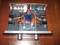
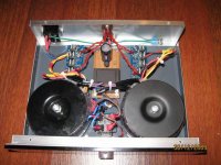
I'm sad to inform u that disaster has struck 🙁 After playing beautifully for several weeks this went wrong. While listening to some loud music suddenly a loud buzz sounded from my right speaker. I quickly shut the amp off. When I looked inside the input wire had made connection with one of the rectifiers on the power board. Looking backwards I have been to sloppy with some of the wires that carry no sleeving. Lesson learned, now for the repair 😉
I just did some measurements, here are the results:
- 34V between V+ and PG+ (seems fine)
- 34V between V- and PG- (seems fine)
- 32.8V offset between the speaker posts with no load (seems huge, the other channel measures 48mV)
- 2V offset between the speak posts with load (seems high, the other channel measures 30mV)
From my measurements I conclude that the damage must be on the amplifier board itself. Since there is not much there (2 caps, 3 resistors and the chip my best guess is that the chip is fried. What do u guys think? Any way I can verify this by measuring?
Thanks!
Regards,
Erik
Hey guys,
I'm sad to inform u that disaster has struck 🙁 After playing beautifully for several weeks this went wrong. While listening to some loud music suddenly a loud buzz sounded from my right speaker. I quickly shut the amp off. When I looked inside the input wire had made connection with one of the rectifiers on the power board. Looking backwards I have been to sloppy with some of the wires that carry no sleeving. Lesson learned, now for the repair 😉
I just did some measurements, here are the results:
- 34V between V+ and PG+ (seems fine)
- 34V between V- and PG- (seems fine)
- 32.8V offset between the speaker posts with no load (seems huge, the other channel measures 48mV)
- 2V offset between the speak posts with load (seems high, the other channel measures 30mV)
From my measurements I conclude that the damage must be on the amplifier board itself. Since there is not much there (2 caps, 3 resistors and the chip my best guess is that the chip is fried. What do u guys think? Any way I can verify this by measuring?
Thanks!
Regards,
Erik
I think you need to replace your chip.
Can someone tell me why I can't reach fully output power/55W or so)? With cd player on I measured around 10V.I think that is 16W with 6ohm speaker.So I need to turn volume up to 50-60% to listen the music.
I'm using Peter's boards with recommended parts(22K,680R,220R,50K pot).
I'm using Peter's boards with recommended parts(22K,680R,220R,50K pot).
With cd player on I measured around 10V.
have you measured the voltage input yet?what voltage are you sending to the amplifier?
I tested with signal generator.1KHz and 400mV.Then measured with osciloscope.At ful pot opened it gives around 10V.
The amplifier gain is 33 so 400mV should give 13V output. Your readings are slightly low but around what is expected.
The other option would be mounting RCAs on non metal plate first (plastic or similar) and then attaching such assembly to the rest of the chassis.
OK, thanks Peter and Bill_P!
Great forum by the way!
10Vac output from 400mVac input indicates a gain of 25times ~+28dB.
That seems to fit the normal gain from a chipamp.
If you want more output voltage you need to supply more input voltage.
I usually measure <2Vac at the output of my amplifiers, when playing music.
That seems to fit the normal gain from a chipamp.
If you want more output voltage you need to supply more input voltage.
I usually measure <2Vac at the output of my amplifiers, when playing music.
Ok.I will do some more testing,but first I have to go drink 😀
Thank you guys and Happy New Year
Thank you guys and Happy New Year
new gainclone builder
Hi Peter,
I bought the pre kit and now have problem with one channel, one offset is 7mV while the other is -35mV.
I am using the SG ground and OG ground as you demonstrated.
The V+ and V- seemed OK. I am using a 50K pot, two amp boards are
the same and there is not anything more to check? Is the chip fried?
Regards,
Jason
Are those the offsets from the amp? If so, they are perfectly fine.
The offset will depend on a particular chip and shunt resistance value (R2) as demonstrated here: http://www.diyaudio.com/forums/audi...-kit-building-instructions-5.html#post1524877
The offset will depend on a particular chip and shunt resistance value (R2) as demonstrated here: http://www.diyaudio.com/forums/audi...-kit-building-instructions-5.html#post1524877
Peter
After successfully completing my first chip amp, i am now looking to build a second amp with a slightly better design. i.e. better case/layout.
I have a set of KEF Q5 speakers which support Biamping, i.e. seperate binding posts for HF/LF.
Have you got a guide/any advice for bi amping and would you use different components on the amp pcb for the high and low frequency channels?
Regards
Dan
Wrong resistors?
Hi,
Received my kit a few days ago. Just started on the soldering.
The R3 resistors in my kit seems to be 751 ohm, not 680 as mentioned in the building instructions. (violet, green, brown, brown). Is this the correct resistors, or have I mixed up something?
By the way: Great service Peter! The "samples" package went through the customs without any tax demands 😉
Regards
Erik
- Home
- More Vendors...
- Audio Sector
- Commercial Gainclone kit- building instructions