Actually, the duct doesnt behave as a compression chamber in my script right now, i only posted it as a starting point for further work. ill update it when i have more time.
without a change in radius, a duct doesnt behave as a compression chamber. thus, you need two ducts in sequence with different radius.
You have to specify a Vf value for the duct element with the smaller radius, which is an acoustic compliance, which is the volume of the crossectional area change of the two ducts. the volume change of two round ducts is Pi*(r1²-r2²)*length2, where the first duct is the bigger one and the second the smaller one.
bottom line: dont take my script as a working one. its in development and you may help 🙂
For those being interested, I put the plans for the Tangband TH on by website into the download section:
Volvotreter Home
Erik
Volvotreter Home
Erik
@MaVo: OK, I'll bite. 🙂
If you look into the AkAbak help file under the examples of the Duct Element, you'll see in the second example that you only need one duct to specify an air chamber (at the entrance) that connects the driver. You could indeed use 2 separate ducts, but this would overcomplicate the script I think.
Maybe there should be a separate AkAbak thread for a TH script, and preferrably with some kind of "AkAbak for Dummies" explanation for people who find the learning process more of a brick wall instead of a curve? (I've been there ... ) 😉
good idea 🙂
then we simply have to change the both ducts to something like:
Duct 'D1' Node=3=5 dD=10cm Len=3cm Vf=50L
to simulate a opening in a 3cm thick wall with the diameter of 10cm and a 50liter compression chamber between driver and wall.
I think this thread is fine for this purpose, as long as others dont complain, as it was also used for the first scripts some months ago.
Edit:
some simple experiments seem to indicate, that the Vf value isnt really needed. substituting the Vf for a duct with the same volume doesnt seem to change the response.
AkAbak
Hi Cordraconis and MaVo: Thanks for the effort, keep on beaten on it. I agree, this thread is fine for all this, and it would also be nice to have an AkAbak for dummies thread. (I started last night, and I definitely qualify.)
If I may make one suggestion, the behavior of 1/4 wave resonating pipes and Helmholtz resonators should be different, and AkAbak should help to show that.🙂
Small THs
Volvotreter: Hi Erik, I downloaded the plans, and the .dwg file will not open in my old Acad 14. Otherwise it looks really straight forward. Thanks
Bye the way the MCM 55-2421 looks good in Hornresp, but, it takes a 5:1 compression ration to get it into a 47 liter box. Reference for measured parameters:
http://www.diyaudio.com/forums/showthread.php?threadid=37908
Attachments
@tb46:
Hi, when did you try? Today I converted the files to AutoCAD 2000 format. Please give it another try and tell me if it works.
On the MCM55: I also tried drivers which peaky response could only be tamed in simulation with small throats only. Finally I avoided these drivers because I think it may be too much and nonlinearity of air compression could be some kind of a problem on higher volumes. But I can not finally judge. Too less knowledge in this regard.
If I remember right GM wrote someting on this furher up. May be he can tell.
Erik
MaVo said:Please post the script you write and also some results, as this seems to be very interesting.
Have you read the patent yet? Somewhere in it, Danley speaks about the use of a front and rear chamber to extend the bandwidth slightly at the cost of steeper rolloff afterwards. Perhaps you could use that for even wider BW and less distortion out of band.
The more I mess around with a midrange tapped horn, the more I think it's not such a hot idea. Not ruling it out entirely, but it's really hard to get flat response. In order to smooth the response, you have to use a high compression ratio, which means you have to resort to novel folding techniques.
I'm trying this with unconventional midranges; a two inch paper cone woofer from tangband.
I've personally measured a pair, so the values I'm using are from "real" production samples.
I believe you could get much smoother response with a midrange tapped horn if you used a prosound mid, like a B&C. But that defeats the purpose in a lot of ways. The B&C has tons of sensitivity and power handling. The TB does not!
If anyone's curious about the TB in a "real" horn, check out my Unity thread.
another unity horn thread
Attachments
Volvotreter said:On the MCM55: I also tried drivers which peaky response could only be tamed in simulation with small throats only. Finally I avoided these drivers because I think it may be too much and nonlinearity of air compression could be some kind of a problem on higher volumes. But I can not finally judge. Too less knowledge in this regard.
Interesting thing, i would also like to know how much compression factor one can use. Has someone experience with this? Somehow i doubt that the air flow will be to fast in a subwoofer as the speed of the air movement is proportional to frequency (at constant excursion), thus more problematic at higher frequencies, but i dont know.
What bad effects can a high compression factor have in a horn (which are not directly viewable in the simulation) ?
@ Patrick Bateman: As the wavelength gets smaller, normal horns are not so big in the midrange, so the advantage of a TH gets smaller with rising frequency. Besides, in the midrange and above, the directivity bonus of a horn is probably the most interesting thing, not the sensitivity bonus, as one can easily produce very high levels without horns.
G'day MaVo
Generally 3:1 is seen as the upper limit when designing bass horns. More than this puts too much stress on the cone, which will soon fail. This rule of thumb applies with pro sound drivers in a pro sound environment, but I believe is applicable at home too. I have seen photos of drivers that have been ripped up in horns with a too high compression ratio, so this is a very real problem. I think in comparison the distortion created when using high compression ratios is a non issue. In the home the levels where this will become significant will be causing plenty of distortion in the structure of the listening room!
Cheers
William Cowan
OK, I'll give it a shot to make an AkAbak for Dummies tutorial during next week. Please keep in mind I only have about 12hours of "experience" with it since I fired it up on David Mc Bean's advice, but maybe that 'll make me able to explain the scripting process in a simple and effective way. 😎
Stay tuned!
@MaVo: I didn't know the Duct and Air chamber volume were interchangeable, dough it makes sense. If I'm not mistaken, there will be tube resonances calculated with the Duct element, while with the Air chamber it is assumed to have an arbitrarily size (more realistic). I won't check this, but maybe you see this in your script.
I have found that if I reduce the mouth size in hornresp on a suitably long TH so that it's near the throat size , the resultant pipe-like enclosure still produces increased sensitivity and extension like a TH. Are these results valid and does this still qualify as a tapped horn?
jnb said:I have found that if I reduce the mouth size in hornresp on a suitably long TH so that it's near the throat size , the resultant pipe-like enclosure still produces increased sensitivity and extension like a TH. Are these results valid and does this still qualify as a tapped horn?
I think that is what tapped horns are all about. The DTS20 has about 1000cm² mouth area. The bigger the mouth gets, the less merit has a th over a similar sized normal horn. So you maybe have mouth which is 2-8 times the throat area, which is fine. It would even work with throat = mouth, at least in theory.
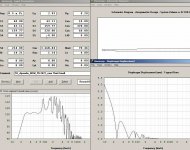
MaVo, you've inspired me. I've worked on your Akabak script and here's what I got.
After studying the photos you posted earlier (do you have more?), I feel the stubs are just single ducts from the front of the driver (no 'T' piece).
I have a simple script and a result to demonstrate it with.
After studying the photos you posted earlier (do you have more?), I feel the stubs are just single ducts from the front of the driver (no 'T' piece).
I have a simple script and a result to demonstrate it with.
Code:
Def_Const |Horn Dimensions

{
a1 = 999e-4; |Area at throat (cm^2)
a2 = 1000e-4; |Area at rear of driver (cm^2)
a3 = 2000e-4; |Area at front of driver (cm^2)
a4 = 2001e-4; |Area at mouth (cm^2)
l1 = 14e-2; |Distance from throat to rear of driver (cm)
l2 = 260e-2; |Line distance from rear of driver to front of driver (cm)
l3 = 30e-2; |Distance from front of driver to mouth (cm)
}

Def_Driver 'Dr1'

| Eminence Delta 15LFA

Sd=856cm2
fs=41Hz
Qes=0.64
Qms=6.65
Vas=186L
Re=6.3ohm
Le=1.49mH

system 'S1'

Driver Def='Dr1' Node=1=0=3=4
Waveguide 'W1' Node=2=3 STh={a1} SMo={a2} Len={l1} Conical
Waveguide 'W2' Node=3=4 STh={a2} SMo={a3} Len={l2} Conical
Duct 'D1' Node=4=0 dD=5cm Len=63cm
Horn 'H1' Node=4 STh={a3} SMo={a4} Len={l3} Conical
Attachments
Nice case study jnb! I wonder how one can change the q of the resonator, to fit the q of the peaks exactly.
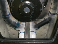
Do you mean the photos of the dts interior? There was a link to an external forum here, where i got those photos, but i cant find it anymore.
Here is the last pic i got:
Do you mean the photos of the dts interior? There was a link to an external forum here, where i got those photos, but i cant find it anymore.
Here is the last pic i got:
Attachments
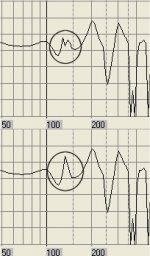
You can alter the effective Q by where you place the stub and how wide the pipe is. I have also had luck placing multiple resonators acoustically near each other for a wider dip.
Looking at the photos I wonder whether the 'T' piece just connects to another stub so as to 'tap' the resonator at one fifth the length or something 😕
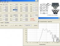
Here is an example of putting a duct at the front, rear or halfway between, and of using multiple ducts at one point.
Looking at the photos I wonder whether the 'T' piece just connects to another stub so as to 'tap' the resonator at one fifth the length or something 😕
Here is an example of putting a duct at the front, rear or halfway between, and of using multiple ducts at one point.
Code:
Def_Const |Horn Dimensions

{
a1 = 999e-4; |Area at throat (cm^2)
a2 = 1000e-4; |Area at rear of driver (cm^2)
a3 = 1500e-4; |Area at half way point
a4 = 2000e-4; |Area at front of driver (cm^2)
a5 = 2001e-4; |Area at mouth (cm^2)
l1 = 14e-2; |Distance from throat to rear of driver (cm)
l2 = 130e-2; |Line distance from rear of driver HALF WAY to front of driver (cm)
l3 = 30e-2; |Distance from front of driver to mouth (cm)
}

Def_Driver 'Dr1'

| Eminence Delta 15LFA

Sd=856cm2
fs=41Hz
Qes=0.64
Qms=6.65
Vas=186L
Re=6.3ohm
Le=1.49mH

system 'S1'

Driver Def='Dr1' Node=1=0=3=5
Waveguide 'W1' Node=2=3 STh={a1} SMo={a2} Len={l1} Conical
Waveguide 'W2' Node=3=4 STh={a2} SMo={a3} Len={l2} Conical
Waveguide 'W2' Node=4=5 STh={a3} SMo={a4} Len={l2} Conical
Duct 'D1' Node=3=0 dD=5cm Len=63cm |AT REAR OF DRIVER
Duct 'D2' Node=4=0 dD=5cm Len=100cm |AT MID POINT
Duct 'D3' Node=5=0 dD=5cm Len=120cm |AT FRONT OF DRIVER
Duct 'D4' Node=5=0 dD=5cm Len=140cm |A SECOND FRONT DUCT
Horn 'H1' Node=5 STh={a4} SMo={a5} Len={l3} ConicalHere is an update for the TH script. I implemented two resonators, front and rear chamber and room effects. Its experimental, so dont sue me for building failures 😉
Def_Const |Horn Dimensions
{
a1 = 315e-4; |Area at throat (cm^2)
a2 = 320e-4; |Area at rear of driver (cm^2)
a3 = 940e-4; |Area at front of driver (cm^2)
a4 = 945e-4; |Area at mouth (cm^2)
l1 = 15e-2; |Distance from throat to rear of driver (cm)
l2 = 350e-2; |Line distance from rear of driver to front of driver (cm)
l3 = 30e-2; |Distance from front of driver to mouth (cm)
vol = 20e-3; | Front and rear compression chamber volume (Liter)
op = 100e-4; | Compression chamber to horn connection size (cm^2)
wl = 1.5e-2; | Compression chamber wall thickness (cm)
r1l = 100e-2; | First resonator length (cm)
r1d = 80e-4; | First resonator area (cm^2)
r2l = 110e-2; | Second resonator length (cm)
r2d = 70e-4; | Second resonator area (cm^2)
rx = 500e-2; | Room width (cm) - the mouth is in the center of the xy plane
ry = 230e-2; | Room heigth (cm) - listening position is at the horn mouth
rz = 600e-2; | Room length (cm)
rd = 0.1; | Frequency independent room damping factor
}
Def_Driver 'Dr1'
| Peerless 830500
Sd=466cm2
fs=18.1Hz
Qes=0.21
Qms=3.7
Vas=139L
Re=3.5ohm
Le=4.2mH
system 'Tapped Horn'
Driver Def='Dr1' Node=1=0=11=21
Duct 'CC1' Node=11=12 Sd={op} Len={wl} Vf={vol}
Waveguide 'W1' Node=2=12 STh={a1} SMo={a2} Len={l1} Conical
Waveguide 'W2' Node=12=22 STh={a2} SMo={a3} Len={l2} Conical
Duct 'CC2' Node=21=22 Sd={op} Len={wl} Vf={vol}
Waveguide 'W3' Node=22=23 STh={a3} SMo={a4} Len={l3} Conical
Radiator 'Mouth' Def='W3' Node=23
|Remove the straight slash below to enable resonators
|Duct 'res1' Node=11=14 Sd={r1d} Len={r1l}
|Duct 'res2' Node=11=15 Sd={r2d} Len={r2l}
|Remove the straight slash below to enable room modelling
|Duct 'Room' Node=23=24 WD={rx} HD={ry} Len={rz} QD/fo={rd}
MaVo, thanks for your continuing efforts. Would you please explain the following to me.
What is the purpose of the compression chambers at each side of the driver? Are they stubs or simply a part of the overall pipe/horn structure, and why have you chosen to run the resonators from node 11?
Does the room sim assume the horn mouth is embedded in half space in the wall and are reflections and standing waves simulated?
jnb said:What is the purpose of the compression chambers at each side of the driver? Are they stubs or simply a part of the overall pipe/horn structure, and why have you chosen to run the resonators from node 11?
Does the room sim assume the horn mouth is embedded in half space in the wall and are reflections and standing waves simulated?
The compresion chambers are there, because they are mentioned in the patend and i wanted to see what they do. They are between each side of the driver and the horn, filtering high frequencies. Just like the ones in the pictures in the patent.
The resonators run from 11, since this is where they seem to be in the DTS20. I thought that would be a good starting point. Move them, if you think another place may be better. Perhaps, 12 would be a more accourate place, but since the dts20 has no compression chamber, i cant know. the resonator placement is subject for individual experimentation.
jnb said:I would also like to find out how to add resistive damping to the resonators.
What is resistive damping? You can make the resonator damp sound by adding a QD/fo value like in the last line of the script.
- Home
- Loudspeakers
- Subwoofers
- Collaborative Tapped horn project