Hi William, as usual, your comments help me alot 🙂
Using 1/4WL resonators in a TH is something i would not have thought of. Same goes for using an inductor, as i have no clue about passive components.
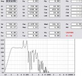
With the new wisdom, i made an attempt to simulate the DTS20 under the assumption, that the driver is a lab12. It looks like one and with Tom being the inventor or the dts20 and labhorn, this assumption lies close. The simulation is attached. The volume of the enclosure seems to fit the size of the dts20. The fact that my simulation has two big peaks and the dts20 has two resonators is indicating some similarity between simulation and real speaker.
And if its not the dts20, its at least a nice 20-60, maybe 100, hz labsub TH 🙂
Using 1/4WL resonators in a TH is something i would not have thought of. Same goes for using an inductor, as i have no clue about passive components.
With the new wisdom, i made an attempt to simulate the DTS20 under the assumption, that the driver is a lab12. It looks like one and with Tom being the inventor or the dts20 and labhorn, this assumption lies close. The simulation is attached. The volume of the enclosure seems to fit the size of the dts20. The fact that my simulation has two big peaks and the dts20 has two resonators is indicating some similarity between simulation and real speaker.
And if its not the dts20, its at least a nice 20-60, maybe 100, hz labsub TH 🙂
Attachments
MaVo_LAB12_TH_Hornresp
Hi MaVo: Looks like you added the series inductance to the Le field in the Hornresp input screen, and that is what helped smoothen the response. To be correct you may have to add the resistance of the series inductor to the Rg field.
Maybe David McBean can comment as to whether or not that approach works with his model?
Yes, i thought that i needed to add resistance, since William also spoke of it, but i dont know how much. As i said, no clue about passive components. Can you give me an equation for this? With added resistance, the horn also needs to be changed. I hope the influence wont be serious 🙂
Series Inductor
Hi MaVo: Here is a link to Parts Express's crossover inductors:
http://www.partsexpress.com/erse-16-gauge-inductors.cfm
it lists typical DCR (ohms).
I still think David McBean's input is needed to see what this does in his Hornresp model.
Hi MaVo: Here is a link to Parts Express's crossover inductors:
http://www.partsexpress.com/erse-16-gauge-inductors.cfm
it lists typical DCR (ohms).
I still think David McBean's input is needed to see what this does in his Hornresp model.
To filter out-of-band resonances, one can use a compression chamber as a high-pass filter, both on the rear and front of the driver. (I'm tinkering on an AkAbak script for that.) Also, those 1/4WL resonators seem te be connected to the front baffle of the driver, rather than separate tubes. This makes me think they could be bass-reflex-like tubes. (Another thing for later, as a short tryout seemd to be promising.)
As one makes a TH smaller, the upper freq go haywire. To compensate for this, one can use built-in acoustical Lowpass filters, but then the size rises again.
However, as said before, if a TH is only to be used as a rather narrow band LF device, it is very *scalable* and less dependant of the driver, compared to most other cabinets I know of.
For some further size reduction, try putting the length of the first segment to 1 (i.e. use a small compression chamber), as this segment mainly serves like a 1/4WL resonator and LP filter. Your electronic crossover will do that instead.
Cordraconis said:To filter out-of-band resonances, one can use a compression chamber as a high-pass filter, both on the rear and front of the driver. (I'm tinkering on an AkAbak script for that.)
I am tempted to ask, why Danley didnt use them, if this is a viable option, since he is the one who knows better than we all do. Well, maybe it is possible but has some tradeoffs he didnt want to make. Please show us the results, if you get some.
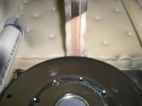
Cordraconis said:Also, those 1/4WL resonators seem te be connected to the front baffle of the driver, rather than separate tubes. This makes me think they could be bass-reflex-like tubes. (Another thing for later, as a short tryout seemd to be promising.)
They are not BR tubes, since they are closed on one end. Ill add a picture which shows that. The open end seems to be right besides the front membrane of the driver.
Cordraconis said:As one makes a TH smaller, the upper freq go haywire. To compensate for this, one can use built-in acoustical Lowpass filters, but then the size rises again.
With lowpass filter, you mean your proposed compression chambers?
Cordraconis said:For some further size reduction, try putting the length of the first segment to 1 (i.e. use a small compression chamber), as this segment mainly serves like a 1/4WL resonator and LP filter. Your electronic crossover will do that instead.
The first length has to have the minimum size of the driver radius in most applications. Also, its combfiltering effect will reduce distortion, as it filters out some frequencies above passband, so using it is a good idea. For best effect, set its length = 1/4WL of your upper cutoff frequency or a bit higher, to put the first notch directly above the passband and get rid of the worst distortions.
Attachments
When surfing on the net i came along the patent about the tapped horn. For someone who`s interested:
http://www.wipo.int/pctdb/en/wo.jsp?wo=2007109075&IA=WO2007109075&DISPLAY=STATUS
There is nothing new in the document, everything is already explained in detail by Tom on several forums. Stil it is an interesting paper to read.
Cheers,
Marcel
http://www.wipo.int/pctdb/en/wo.jsp?wo=2007109075&IA=WO2007109075&DISPLAY=STATUS
There is nothing new in the document, everything is already explained in detail by Tom on several forums. Stil it is an interesting paper to read.
Cheers,
Marcel
@ Cordraconis: The patent speaks of the use of front and rear chambers, tuned for lowering the out of the passband distortion. so you were right. i hope you can model this in akabak 🙂
Re: MaVo_LAB12_TH_Hornresp
Hi tb46,
As far as Hornresp is concerned, increasing the values of Le and Rg (and/or Re) is the same as placing an inductor and resistor in series between the amplifier constant voltage source and the driver.
Kind regards,
David
tb46 said:Hi MaVo: Looks like you added the series inductance to the Le field in the Hornresp input screen, and that is what helped smoothen the response. To be correct you may have to add the resistance of the series inductor to the Rg field.
Maybe David McBean can comment as to whether or not that approach works with his model?
Hi tb46,
As far as Hornresp is concerned, increasing the values of Le and Rg (and/or Re) is the same as placing an inductor and resistor in series between the amplifier constant voltage source and the driver.
Kind regards,
David
Marcello: Thanks for the link, the drawings answer some questions.
David McBean: Thanks for clarifying that.
🙂
David McBean: Thanks for clarifying that.
🙂
http://www.diyaudio.com/forums/attachment.php?postid=1426385&stamp=1202828040&
looks like the driver plays into the horn at three places, not 2...
looks like the driver plays into the horn at three places, not 2...
no, just two.Chris8sirhC said:http://www.diyaudio.com/forums/attachment.php?postid=1426385&stamp=1202828040&
looks like the driver plays into the horn at three places, not 2...
The front drives the cutout, the back is tapped into the exit length about half the height up from the end. It looks like a neat way to make S1 and S3 different.
cowanaudio said:G'day MaVo
They are resonators tuned to the same frequency as the first few response peaks. You'd probably find that each branch is 1/4 WL of each peak in question. The ~5mH series inductor flattens the response and removes some of the higher frequency stuff (It's DCR doesn't hurt in many cases, too).
Cheers
William Cowan
WOW!
I can't remember the last time I was so excited to run home and fire up Akabak! Those resonators change EVERYTHING. They open up the possibility of squeezing three octaves of bandwidth out of these things.
I've been trying to figure out a way to use a tapped horn for a midrange, and that's JUST THE TICKET.
I'd like to create a midrange which could cover 200hz to 1.6khz, with massive efficiency and a small footprint.
Picture a midrange enclosure the size of one of those petite little audiophile speakers, but with the dynamics of a Klipschhorn, and you'll get an idea of where I'm going with this.
Please post the script you write and also some results, as this seems to be very interesting.
Have you read the patent yet? Somewhere in it, Danley speaks about the use of a front and rear chamber to extend the bandwidth slightly at the cost of steeper rolloff afterwards. Perhaps you could use that for even wider BW and less distortion out of band.
Have you read the patent yet? Somewhere in it, Danley speaks about the use of a front and rear chamber to extend the bandwidth slightly at the cost of steeper rolloff afterwards. Perhaps you could use that for even wider BW and less distortion out of band.
As there seems to be some demand for a updated TH akabak model, i made a start to script one. I took williams model from his homepage and added two ducts. One between the driver front and the TH and one between the driver rear and the TH.
This is by no means a good solution at simulating compression chambers, but i have exams soon and not much time to fool around. i invite everyone who wants to get a more accurate simulation of the compression chamber.
One way is described in the akabak manual on page 182 under the topic of "diaphragm cones as duct". one has to use two ducts per compression chamber, because the compression chamber will be bigger in diameter than the opening to the tapped horn, so one duct is the chamber and one is the opening in the wall to the waveguide part of the horn. the second has a transition compliance which has to be computed somehow. it is dependant on the ratio of diameter between the two ducts. the compliance models the air getting compressed in the chamber, while the ducts itself only is for displacing air over its length. Further improvements could be the addition of resonators, which can be modelled by ducts as well.
here is my crude attempt with added ducts, as a starting point:
(thanks to William Cowan for the basic script, that safed me a lot of work)
Def_Const |Horn Dimensions
{
a1 = 315e-4; |Area at throat (cm^2)
a2 = 320e-4; |Area at rear of driver (cm^2)
a3 = 940e-4; |Area at front of driver (cm^2)
a4 = 945e-4; |Area at mouth (cm^2)
l1 = 15e-2; |Distance from throat to rear of driver (cm)
l2 = 350e-2; |Line distance from rear of driver to front of driver (cm)
l3 = 30e-2; |Distance from front of driver to mouth (cm)
}
Def_Driver 'Dr1'
| Peerless 830500
Sd=466cm2
fs=18.1Hz
Qes=0.21
Qms=3.7
Vas=139L
Re=3.5ohm
Le=4.2mH
system 'S1'
Driver Def='Dr1' Node=1=0=3=4
Duct 'D1' Node=3=5 dD=30cm Len=30cm
Waveguide 'W1' Node=2=5 STh={a1} SMo={a2} Len={l1} Conical
Waveguide 'W2' Node=5=6 STh={a2} SMo={a3} Len={l2} Conical
Duct 'D2' Node=4=6 dD=30cm Len=30cm
Horn 'H1' Node=6 STh={a3} SMo={a4} Len={l3} Conical
@MaVo: At page 42 of this thread, I already posted a crude script. If you remove/adjust the "resonator" part, you get the script you were looking for, albeit less ... elegant 😉 ... than yours.
I hadn't read the patent yet - tomorrow I have a day off and then I'll will - but the picture is almost exactly what I had in mind.
The resonators of tb46 were spot on by the looks of it, but I misunderstood what he meant and tried to apply them to the LF part which lead me to dismiss them and research passive radiators instead.
MaVo, how do you feel your Akabak script rivals Hornresp for accuracy? I'm considering learning it so that I can do the resonators.
akabak can model stuff like front and rear compression chambers, resonators, room effects, unusual geometries, etc. which are not possible in hornresp. the akabak script that i use, which william cowan wrote, is as good as hornresp, i think (but in its current state with the added ducts, its no good). hornresp is alot easier to use and gives fast and accurate results. both are fine, it depends on what you want to do. for a normal th, use hornresp, if you want to add the above mentioned things, use akabak.
Mr. Mc Bean explained: "Hornresp and AkAbak tapped horn simulation results are normally identical, provided that the systems being compared have equivalent specifications."
If you specify a volume in MaVo's "Duct" elements, you'll add a compression chamber of said volume. The length of the ducts are also quite long (I'd use 12 or 18mm, i.e. the thickness of the MDF) With this long ducts, I believe the chambers will react as a bass-reflex where the port loads the tapped horn. Using ducts of a length with equal thickness of the construction material seems more appropriate to me (and not to mention a LOT more easy to construct.)
If you specify a volume in MaVo's "Duct" elements, you'll add a compression chamber of said volume. The length of the ducts are also quite long (I'd use 12 or 18mm, i.e. the thickness of the MDF) With this long ducts, I believe the chambers will react as a bass-reflex where the port loads the tapped horn. Using ducts of a length with equal thickness of the construction material seems more appropriate to me (and not to mention a LOT more easy to construct.)
- Home
- Loudspeakers
- Subwoofers
- Collaborative Tapped horn project