JHL, I saw the pictures you had posted a while back and also here, did you ever post diagrams with measurements? If so where?
Why wouldn't I want to build precisely what you have drawn in sketch up?
You seem pleased with the results. If you haven't posted actual plans, and you feel this is a worthwhile design, I would appreciate being able to build one or two.
Paul
Why wouldn't I want to build precisely what you have drawn in sketch up?
You seem pleased with the results. If you haven't posted actual plans, and you feel this is a worthwhile design, I would appreciate being able to build one or two.
Paul
aceinc said:JHL, I saw the pictures you had posted a while back and also here, did you ever post diagrams with measurements? If so where?
Why wouldn't I want to build precisely what you have drawn in sketch up?
You seem pleased with the results. If you haven't posted actual plans, and you feel this is a worthwhile design, I would appreciate being able to build one or two.
Paul
I have an improved model which needs to be built first. (more bandwidth and smoother response) Once I get the folding down on paper, I'll share my plans with the forum. If you guys want to beat me to the actual build, that's fine with me. Its really too cold here to build much.
Rgs, JLH
JLH, I took the numbers you posted on page 95 and ran them through hornresp. I am still using version 17.something of hornresp, it won't let me model more than a single driver so I just halved everything except length. Impressive physical size vs spl output ratio, but I noticed that you should be hitting xmax with about 100 watts per driver (200w combined) so I'm not sure how you're able to hit em with 600w (which is also way more than rated Pe).
Anyway, your comment about trying not to use an inductor prompted me to look up the price of inductors. Now I don't want to use an inductor either. So back to the drawing board to come up with a design for my drivers that does not need an inductor. The answer (the first solution I came up with) is a lower tuning. This also helps to provide a gently rising response as well. Look ma, no coil!
20 hz tapped horn, 84L, 80w
At 84L it's getting pretty large but that seems to be what's required to tune low enough to calm the squiggles down.
JLH's dual driver horn seems to be right around 200L or so and hornresp says it would take 4 of these 85L boxes to match the output of his single sub, so wrt physical size vs output, his beats this hands down, but I still don't think this is too bad. This low tuning is just another possible way to git er done I guess.
Anyway, your comment about trying not to use an inductor prompted me to look up the price of inductors. Now I don't want to use an inductor either. So back to the drawing board to come up with a design for my drivers that does not need an inductor. The answer (the first solution I came up with) is a lower tuning. This also helps to provide a gently rising response as well. Look ma, no coil!
20 hz tapped horn, 84L, 80w
An externally hosted image should be here but it was not working when we last tested it.
An externally hosted image should be here but it was not working when we last tested it.
At 84L it's getting pretty large but that seems to be what's required to tune low enough to calm the squiggles down.
JLH's dual driver horn seems to be right around 200L or so and hornresp says it would take 4 of these 85L boxes to match the output of his single sub, so wrt physical size vs output, his beats this hands down, but I still don't think this is too bad. This low tuning is just another possible way to git er done I guess.
just a guy said:JLH, I took the numbers you posted on page 95 and ran them through hornresp. I am still using version 17.something of hornresp, it won't let me model more than a single driver so I just halved everything except length. Impressive physical size vs spl output ratio, but I noticed that you should be hitting xmax with about 100 watts per driver (200w combined) so I'm not sure how you're able to hit em with 600w (which is also way more than rated Pe).
Anyway, your comment about trying not to use an inductor prompted me to look up the price of inductors. Now I don't want to use an inductor either. So back to the drawing board to come up with a design for my drivers that does not need an inductor. The answer (the first solution I came up with) is a lower tuning. This also helps to provide a gently rising response as well. Look ma, no coil!
20 hz tapped horn, 84L, 80w
An externally hosted image should be here but it was not working when we last tested it.
An externally hosted image should be here but it was not working when we last tested it.
At 84L it's getting pretty large but that seems to be what's required to tune low enough to calm the squiggles down.
JLH's dual driver horn seems to be right around 200L or so and hornresp says it would take 4 of these 85L boxes to match the output of his single sub, so wrt physical size vs output, his beats this hands down, but I still don't think this is too bad. This low tuning is just another possible way to git er done I guess.
The 600W input was on the 8PS21 dual tapped horn I built. I never released the details of the 8PS21 dual tapped horn to the forum. I think you are confusing the 8PS21 one with the W8-740 one.
When I tested the 600W into the 8PS21 tapped horn it was with music program. The 600W input probably occurred somewhere around 50Hz to 65Hz range. I knew the highest reading on my meter read 48.2Vrms into the 4 ohm load of the tapped horn. Therefore my testing was frequency independent. If I ever exceeded Xmax it was not audible. My educated guess is there was not enough low frequency content in the music program to exceed Xmax at 600W input.
The initial indications from my improved W8-740 dual tapped horn looks like it will be around 130L. I raised the tuning to 30Hz because I don’t need flat response to 20Hz due to room gain. Worst case for Xmax limited SPL should be around 117dB at any frequency in 2Pi space. What this means for me is 1 will be enough, but I’ll still end up with a stereo pair.
JLH,
First, thank you thank you for sharing your TB TH. That one is a manageable size. In fact, it just might be perfect for fitting between the joists in my basement ceiling with the mouth of the TH venting up into my living room floor (like heat vents). I had been thinking of doing an IB manifold this way, but this gives me another idea.
You wouldn't happen to have a dimensioned drawing, by hand or otherwise would you?
Josh
I think you are confusing the 8PS21 one with the W8-740 one.
You are correct sir, I did not know you had more than one. Thanks for setting me straight.
You wouldn't happen to have a dimensioned drawing, by hand or otherwise would you?
JLH's w8-740 tapped horn drawings are on page 95 and 107.
EDIT- oh you wanted dimensions. Never mind. You won't find those on page 95 or 107.
Here I am again with new stupid questions
Regarding JHLs neat design, could we call it a compression TH
When I first looked at tapped horns it was mostly because of its very simple construction, very convenient
The JHL design has besides playing dawnwards 3 other options fore the woofer "front" openings
The woofers could play backwards out into the end of the line
They could play freely out the sides
Or play out at the front
But the last two, playing out at the front or sides would mean that its no longer a tapped horn, but to be considered as a backloaded
Is there any good reason fore choosing one over the other
Tinitus, it's been explained and shown many times that when you have the driver right at the beginning and end of the line it operates just like a (chambered or not) scoop bin. This is mainly the reason I am still undecided on the chamber, since there's really nowhere else inside a tapped horn to put one.
So you could call JLH's a tapped horn or a blh but in the end performance is all that matters.
To illustrate this, make a tapped horn in hornresp. Keep the driver right at the beginning and end of the line. Try it once. When it asks if you want to model a tapped horn say yes. Try it again and this time say no to tapped horn. The model will be exactly the same. Unless the driver is up into the horn a bit it models exactly like a blh.
JLH's TH does not have a compression chamber and is not a back loaded horn.
It is a dual driver TH with a high S1 value.
The slight difference is that he has reversed one of the drivers, physically and electrically, to make them work in push pull mode as he explained. This helping to reduce distortion, particularly at higher cone displacements.
JLH,
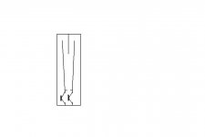
can you confirm that the mouth (exit) is at the left side of the drawing?
It is a dual driver TH with a high S1 value.
The slight difference is that he has reversed one of the drivers, physically and electrically, to make them work in push pull mode as he explained. This helping to reduce distortion, particularly at higher cone displacements.
JLH,
can you confirm that the mouth (exit) is at the left side of the drawing?
FWIW, because I have selected a different setting to most people it seems, this is page 54 for me. Post numbers are far more useful references.just a guy said:
JLH's w8-740 tapped horn drawings are on page 95 and 107.
EDIT- oh you wanted dimensions. Never mind. You won't find those on page 95 or 107.
JLH's TH does not have a compression chamber and is not a back loaded horn.
You sure about that? Go to the the previous page of this thread to see pics of JLH's tapped horn. It absolutely does have a compression chamber, and while names are largely semantics, it models the same as a blh.
Yes, ofcourse, thanks
Sitting thinking about making the woofer "opening" as a series of holes, dawnwards and backwards, and maybe on front too...probably no difference 🙄
Sitting thinking about making the woofer "opening" as a series of holes, dawnwards and backwards, and maybe on front too...probably no difference 🙄
AndrewT said:
JLH,
can you confirm that the mouth (exit) is at the left side of the drawing?
Those drawings are difficult and tricky
But your question is interesting...making me think whether it would be good to have the mouth openings at both sides...to me it looks like it a natural option
just a guy said:
You sure about that? Go to the the previous page of this thread to see pics of JLH's tapped horn. It absolutely does have a compression chamber, and while names are largely semantics, it models the same as a blh.
Yep, a driver-in-mouth folded horn after Olson. For the typical simple end loaded TH I calc a variation of the BIB (AKA expanding TL).
GM
Actually if you look at the JLH's pics the drivers are only a few cm from the mouth. But in the hornresp inputs they are listed as quite a way in, so I'm not even sure if I'm confused or if the hornresp inputs don't match the drawing.
??? If you're referring to the SketchUp? renderings, the drivers are in a low pass filter chamber (folks have been erroneously calling them compression chambers) just inside the terminus feeding a slot filtered BLH, so what am I missing?
GM
GM
Those drivers might measureably be 30 or so cm from the mouth, but they are not 30 cm from the end of the line length, so whatever. I'm not sure the hornresp inputs accurately reflect the drawing, that's all.
I'm getting on thin ice here as I don't know enough to back up what I just said. So I'll leave it alone now.
(I mentioned before that it models like a blh. What I meant was that it should model like a blh. The hornresp model actually is not similar to a blh though)
I'm getting on thin ice here as I don't know enough to back up what I just said. So I'll leave it alone now.
(I mentioned before that it models like a blh. What I meant was that it should model like a blh. The hornresp model actually is not similar to a blh though)
- Home
- Loudspeakers
- Subwoofers
- Collaborative Tapped horn project