
I'm afraid altering the feedback resistors would have side effects. CFA usually works best with low value feedback resistors, also in a CFA the feedback resistors are part of the compensation circuit. I'll have a look at the simulation and see what the changed feedback resistors do to the loop gain plot, then come back to you.Let me draw your attention to post #251 again - upping the values of the resistors in the feeback loop is essential for low distortion.
Which modifications are included on this layout?Are the values on the board the correct ones?
Are the resistors the same if you use bc550/560 or BD139/140?
Are the resistors the same if you use bc550/560 or BD139/140?
Hi MrHifiTunes,
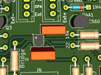
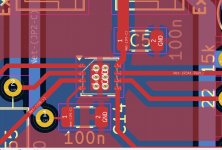
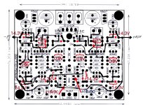
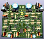
no modifications, just the original values. But take a look at the attachment. I have marked the places.
Change the 8 x15 k to 5,1k, 4x 22 to 6,8R and the OPA outputresistor from 100 to 22R. Instead of 5,1k resistors it is possible to set CRD 3,5 mA diodes.
The BD139/140 i have set for other users. No known modification with them until yet.
If all modifications done, i change the values etc
Attachments
Changing the 15k and 22R are the changes chalky worked out right?
Were they an improvement over the original? Did some people tried them?
Are the bc550/560 the best option?
I'm at the point of ordering the components. Or is it better to wait a bit till everything clears out more?
Were they an improvement over the original? Did some people tried them?
Are the bc550/560 the best option?
I'm at the point of ordering the components. Or is it better to wait a bit till everything clears out more?
Consider CRDs, which are very awesome parts. Current Regulated Diode. Much, much more expensive than resistors, but they will provide regulated current. They should be much better than resistors. Buy in quantity ten to screen for matched pairs. Since you are ordering parts, might as well get them. About $7.77 USD for 10 Semitec.
To pair the CRDs just measure the current; its nominally 3.5mA but there's a spread of 3.0 to 4.1mA according to the datasheet
Let me draw your attention to post #251 again - upping the values of the resistors in the feedback loop is essential for low distortion.
As promised here is the loop gain plot before/after the feedback resistor value change. Just as expected, with high resistor values (10x), the CFA lost its bandwidth by about a decade, unity gain crossover frequency at 719KHz vs 6.3MHz, lost loop gain at 20KHz by almost 20dB, 31dB vs 50dB. Also at about 2nd pole frequency there came this sharp peaking, where in the "before" plot a nice, well damped knee, although this peaking response may not cause any issue as it's way down in amplitude and far out in frequency. It seems to me by using high value feedback resistors we are move away from the merit a CFA would otherwise deliver.


Whats the distortion like? Bit of a trade off here because the current values of the feedback resistors are too low for a 1mA output quiescent current and lower than ideal for a 10mA output current. Perhaps doubling the values of the feedback resistors and increasing the quiescent current to 30mA would be a better compromise. If you did this you'd need heatsinks on the output transistors.
About the same. The simulation clearly shows the action. By upping the feedback resistor values the out put moved away from current starvation and stays in class-A, this would reduce distortion by 10 folds, however, since we now also lost loop gain by about that much, we end up seeing more or less the same distortion figure.Whats the distortion like?
So, if distortion is important, (of course it is, a starved diamond is a broken diamond) we'd need to make up mind on the maximum output amplitude, and the total output current (including the current the feedback networks consumes), then work out the minimum output stage bias current to keep it in class-A.
I guess in the interests of dynamic range it might be worth working back from the highest highest feasible output quiescent current, probably around 35mA with the AliExpress pcb. You could simulate that with the current resistor values and maybe a 2x increase to see if that gets you anything.
I guess too that we would have been much better off if the vas transistor had been a darlington pair.
This link on "Biasing Op-Amps into Class A" was recently posted in another thread. Interesting reference to CRDs.
Hi
i am not really finished...lot to do at my work.
kr
chris
i am not really finished...lot to do at my work.
- my proposal is to use a low current Regulator. the 500mA 7815 has a better noise level then a "normal" 7815 with 1A.
cost is less and the function is a bit better for this preamp. - as written above post 267- change the resistors to the values that you have a bit more current.
the 15k - you can solder 2 in parallel - you get about 7k
22R - use 3 pcs the you get about 7R - OPA output resistor to 22R
kr
chris
- Home
- Amplifiers
- Solid State
- Clon C-3850