Hi Peter,It is only subjective, reference are my ears...
Try to learn to use some spectrum analysis software like Arta. All you need for amatheur purposes are: software, a low distortion 1kHz oscillator, a low distortion sound card and time.
Once you measure distortion of individual devices you can allocate the culprit for bad sound. Otherwise everything is guesswork based on subjective perceprion.
Yep, i have to learn. A friend of mine gave this to me https://de.elv.com/p/elv-serie-7000-elv-mini-funktionsgenerator-mg-7000-P204251/
I have an Arta lincense and cant use it....🙂
I think my soundcard is not to bad. It is an Asus Essence ST or STX, different computers...
Peter
I have an Arta lincense and cant use it....🙂
I think my soundcard is not to bad. It is an Asus Essence ST or STX, different computers...
Peter
Back to the 3850 Clone. I had soldered the BD 139/140 in. But i had a problem to find 2 equal pairs. I have 42 transistors in stock, CDIL, ST. I think one pair is ok with 136 hFE /687 mv and 138 hFE 683 mV Vbe, the second one i am not sure 145 hFE/689 mv and 150 hFE/689 mV Vbe. Vbe is very similar...
New test...
The Sound does not change with the BD transistors. But i get hum on one channel, nothing to do with the new transistors, i can say afterwards.
I soldered the old BC 550 and BC 560 back. The hum remained. I dont know the cause for the hum. I soldered every pad new and it is gone now.
The BC transistor pairs are not equal too. BC560 484 hFE/757 mV, 467 hFE/758 mV, BC550 513 hFE/745 mV, 508 hFE/743 mV Vbe, on my board.
I changed the OPA to AD828 with Adapter, LM4562, LME49720, OPA 2604. Some more will follow...In the moment i most like the sound of the OPA2604.
The AD828 i have to hear for a longer time.
I am pleased that the bad sound is gone now. I dont sure what the cause was....
Bad news... there is a little white noise in my AMT Speakers. You have to put the ear on to hear it, but it is there. I have connected different Amps, always the same.
The white noise is a no go for me. I dont remember if it was there before i changed the output resistor at the opa. I will try 47 ohm...
I took much to long to test little things out.
Greets
Peter
I have an oscilloskope with built in function generator but such sinewave isn't precise enough for this task. I am using Akitika 2ppm Oscillator.
https://www.akitika.com/1kHzOscillator.html
It cost me about 100 bucks + pain of the EU mport process for the US products.
https://www.akitika.com/1kHzOscillator.html
It cost me about 100 bucks + pain of the EU mport process for the US products.
I own this... https://www.amazon.de/OWON-Oscilloscope-2-Channel-Oscilloscopes-Bandwidth/dp/B07TCF1BNP
I have all needful things...😎
You are right...i have to learn to use them...
Peter
I have all needful things...😎
You are right...i have to learn to use them...
Peter
Apologies for an OT question. Can you share the great DAC board?I have put together a great DAC board into a chasis together with MBL6010D preamp clone based on AD797 opamps. In addition to that I have used regulated power supples, even for 5V digital part. The beast beats any commercial DAC. You just have to dare do it...
But of course.Can you share the great DAC board?
XingCore USB card (search here at this forum to find positive opinion from trustworthy members)
https://www.aliexpress.com/item/400...order_list.order_list_main.175.46d018029IkEYE
Decoder and power supply:
https://www.aliexpress.com/item/100...order_list.order_list_main.185.46d018029IkEYE
Thank you. PCM1794 is an excellent DAC. Sorry, just one more question. PCM1794 running OS or NOS?
You're welcome. I use it with Windows 10, but I don't know if Xingcore have drivers for Mac too. Please visit xingcore.com for more info.
Last edited:
Getting back to distortion measurements, the current USB audio interfaces are very capable and inexpensive. A Focusrite Scarlett has 120dB SNR or so. The included DACs are really good enough as signal generators for cheapskates like me. Running on battery is a necessity. Getting a test setup with proper grounding and shielding can be very challenging. As a practical matter, knowing that the device under test can perform to the level of current USB interfaces is really good enough for me.
Answering my own question, I think the paralleled PCM1794 DAC above is OS. The nice thing about the 1794, is that in mono mode the built-in OS filters are turned off. NOS DAC versions also have two 1794 chips, one for the right channel and the other for left channel.
Answering my own question, I think the paralleled PCM1794 DAC above is OS. The nice thing about the 1794, is that in mono mode the built-in OS filters are turned off. NOS DAC versions also have two 1794 chips, one for the right channel and the other for left channel.
Building the board with the initial components to get it work.Later I will do some modifications.
Question about matching the NPN/PNP transistor.
Which needs to be matched?
Do you match on Hfe or Ube or ...
What is "a match"? How different is torable?
Question about matching the NPN/PNP transistor.
Which needs to be matched?
Do you match on Hfe or Ube or ...
What is "a match"? How different is torable?
Hey I just wanted to share that my C3850 kit was just a bit different than what I see from the schematic posted in @chalky mod post #177.
I've got a board with the 3 relays, and it is labeled V1.4
Front

Back

So final resistor pair is a bit different,
R24, R25 = 15 (instead of 22)
Also, I've got different transistors. The board is labeled for A1015 / A733 and C1815 / C945, but the final pair changes to ZTX450 and ZTX550. The components delivered with my kit were A733 and C945 (and the ZTX's).
Does this difference seem to be of any substance to the brain trust?
I've got the 6.8 Rs and the CRDs to swap in. Can anyone confirm the orientation for the CRDs in this board?
Thx -
Adam
I've got a board with the 3 relays, and it is labeled V1.4
Front
Back
So final resistor pair is a bit different,
R24, R25 = 15 (instead of 22)
Also, I've got different transistors. The board is labeled for A1015 / A733 and C1815 / C945, but the final pair changes to ZTX450 and ZTX550. The components delivered with my kit were A733 and C945 (and the ZTX's).
Does this difference seem to be of any substance to the brain trust?
I've got the 6.8 Rs and the CRDs to swap in. Can anyone confirm the orientation for the CRDs in this board?
Thx -
Adam
HiBuilding the board with the initial components to get it work.Later I will do some modifications.
Question about matching the NPN/PNP transistor.
Which needs to be matched?
Do you match on Hfe or Ube or ...
What is "a match"? How different is torable?
ideally first VBE match...then hfe match.
use your tool (e.g. DCA75pro) and sort all transistors on big paper with notes on the table.
what is match:
matching is the try to get the ideal pair between both "polarized" transistors. Vbe is the voltage when the transistor is start opening with a base current.
hfe is the relation between bias current and collector (ic) current.
kr
chris
I have tested the output transistors with the smaller Atlas component tester. You can read about the result in post 303. Try to find pairs with hFE and Vbe as close as possible. You will need a lot of transistors to find pairs which are very close. http://www.diamondstar.de/transistor_matching_bjt.html (easy answer)
Greets
Peter
Greets
Peter
They have a cathode ring mark, which connects to the negative voltage potential. The opposite lead (anode) connects to the positive voltage.I've got the 6.8 Rs and the CRDs to swap in. Can anyone confirm the orientation for the CRDs in this board?
Thx -
Adam
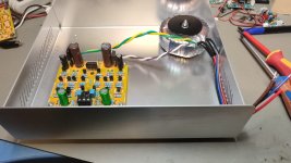
good evening
small progress...
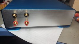
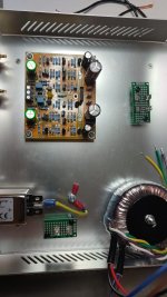
housing and RCA, transformer and pcb setup okay.
i need 230V socket and wires,fuses, cabling, testing
i bought that housing for small Class D amp in 2021. available in blue, gold and black
housing
kr
chris
small progress...
housing and RCA, transformer and pcb setup okay.
i need 230V socket and wires,fuses, cabling, testing
i bought that housing for small Class D amp in 2021. available in blue, gold and black
housing
kr
chris
Attachments
I subbd in the CRDs (and changed the 15R (22R for others) to 6.8) on my functioning stock board. I ended up with 14 v dc at the input and output, and the LM337 became hot after 10-15 sec. I looked around a bit but couldn't tell why. I pulled the CRDs (afterword they measured at the same current flow as before I inserted them) and moved to the 5.1k resistors and that config seems to function just fine.
Sonically, it might have improved resolution? But the time to take it from one config to the other prevents a tight A/B so it's hard to say for sure. I thought it sounded fairly nice before, and think it sounds fairly nice after.
Sonically, it might have improved resolution? But the time to take it from one config to the other prevents a tight A/B so it's hard to say for sure. I thought it sounded fairly nice before, and think it sounds fairly nice after.
Hi
small step forward,
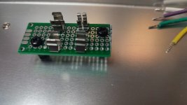
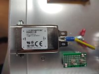
schaffner filter HF filter (without fuses but switch -digikey) is 1A. so keep in mind that the transformer can have 2A primary (noratel 50VA) but you should use 1A fuses because the schaffner HF filter can handle just 1A.
secondary of the transformer can handle 2x 315mA...so that is not needed for your pre amp ...so i guess 100mA should be enough.
is use a small pcb for hold the fuses 5x20mm) ... keep in mind that you should use for safety reason nylon stand offs and nylon screws. every better solution for fuses in my case is very welcome.
chris
Attachments
- Home
- Amplifiers
- Solid State
- Clon C-3850

