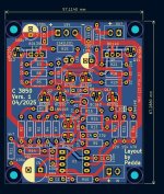
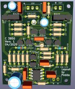
I found some Burr Brown buf634 in my parts pile, and will try build the c-3850 with those as buffer, also i skipped the dc servo and pass the signal through quality capacitor.
Anyone tried something similar?
Anyone tried something similar?
Trying to sort out the direction of the CRD on the board. Its direction is from + to -, towards the base of the 550 and away from the base of the 560 ( correct me if I’m wrong). So, the easiest way for me is to post a picture of how I believe it’s the right way. But I’m not 100% sure….

Post 317...
"They have a cathode ring mark, which connects to the negative voltage potential. The opposite lead (anode) connects to the positive voltage."
"They have a cathode ring mark, which connects to the negative voltage potential. The opposite lead (anode) connects to the positive voltage."
Than I’ve interpret it right. The picture posted in #566 made me a bit confused…. Seems the crd are mounted the wrong way????Post 317...
"They have a cathode ring mark, which connects to the negative voltage potential. The opposite lead (anode) connects to the positive voltage."
The direction in my picture above should be right.
The markings below are right, yes???
Thanks 🙏
Bought a OPA1612 DIP8. How should I insert it in the socket? Notch towards the inputs? Is there anything I must change in the circuit to properly use it instead of standard 5532?

Hi
in your pic the left lower corner is pin1 and then ccw (counter clock wise) order the pins are counted.
on the black chip you see a dot in the left right corner - so that is the initial point where you shoukd insert exactly the chip like your NE5532.
the markings on NE5532 are there too! --PIN 1
the OPA1612 is pin compatible like NE5532


kr
chris
in your pic the left lower corner is pin1 and then ccw (counter clock wise) order the pins are counted.
on the black chip you see a dot in the left right corner - so that is the initial point where you shoukd insert exactly the chip like your NE5532.
the markings on NE5532 are there too! --PIN 1
the OPA1612 is pin compatible like NE5532
kr
chris
Hi OnklePHThan I’ve interpret it right. The picture posted in #566 made me a bit confused…. Seems the crd are mounted the wrong way????
The direction in my picture above should be right.
The markings below are right, yes???
View attachment 1446029
Thanks 🙏
yes this is correct.
read throug the post 177 - chalky is writting this there.
".. These look just like little 1n4148 small signal diodes but are in fact tiny ICs using a jfet and resistor to set the current. So the 15k resistors R12, R16, R19 and R21, which set the diamond quiescent current can be replaced with 3.5mA CRDs. This will up the hfe of all of the transistors and set the quiescent current of the vas transistors Q4 and Q10 to 7mA, solidly into class A with increased hfe. The emitter resistors of Q6 and Q12 can be reduced from 22R to 6.8R which will increase the quiescent current through these transistors to about 11mA, so they should run in class A even at the maximum output swing. You can get the CRDs ( they call them current limiting diodes ) from AliExpress at a reasonable price. Search for "current limiting diodes" and select the E-352. There is a bit of variation in the current between diodes and its best if the pair of CRDs for each diamond are matched - shouldn't be a problem because the best price for these parts on AliExpress are in a pack of 10 and that should be enough to get two matched pairs. If anyone wants to try this and is uncertain about how to use and match CRDs I can explain. Even if you dont want to try the CRDs reducing R12, R16, R19 and R21 from 15k to 5.1k will set the currents to the same level as the CRDs would. Don't forget to change the change emitter resistors of Q6 and Q12 from 22R to 6.8R...."
kr
chris
ps
the pic in post 566 is really confusing- looks like wrong direction and parallel to a resistor...not clear for me.
Bought a OPA1612 DIP8. How should I insert it in the socket? Notch towards the inputs? Is there anything I must change in the circuit to properly use it instead of standard 5532?
View attachment 1446045
Beware of fake chip.
where you bought them?
Thanks @chermannHi OnklePH
yes this is correct.
read throug the post 177 - chalky is writting this there.
".. These look just like little 1n4148 small signal diodes but are in fact tiny ICs using a jfet and resistor to set the current. So the 15k resistors R12, R16, R19 and R21, which set the diamond quiescent current can be replaced with 3.5mA CRDs. This will up the hfe of all of the transistors and set the quiescent current of the vas transistors Q4 and Q10 to 7mA, solidly into class A with increased hfe. The emitter resistors of Q6 and Q12 can be reduced from 22R to 6.8R which will increase the quiescent current through these transistors to about 11mA, so they should run in class A even at the maximum output swing. You can get the CRDs ( they call them current limiting diodes ) from AliExpress at a reasonable price. Search for "current limiting diodes" and select the E-352. There is a bit of variation in the current between diodes and its best if the pair of CRDs for each diamond are matched - shouldn't be a problem because the best price for these parts on AliExpress are in a pack of 10 and that should be enough to get two matched pairs. If anyone wants to try this and is uncertain about how to use and match CRDs I can explain. Even if you dont want to try the CRDs reducing R12, R16, R19 and R21 from 15k to 5.1k will set the currents to the same level as the CRDs would. Don't forget to change the change emitter resistors of Q6 and Q12 from 22R to 6.8R...."
kr
chris
ps
the pic in post 566 is really confusing- looks like wrong direction and parallel to a resistor...not clear for me.
kr
Per
Here’s from the data sheet of the CRD E-352Hi OnklePH
yes this is correct.
read throug the post 177 - chalky is writting this there.
".. These look just like little 1n4148 small signal diodes but are in fact tiny ICs using a jfet and resistor to set the current. So the 15k resistors R12, R16, R19 and R21, which set the diamond quiescent current can be replaced with 3.5mA CRDs. This will up the hfe of all of the transistors and set the quiescent current of the vas transistors Q4 and Q10 to 7mA, solidly into class A with increased hfe. The emitter resistors of Q6 and Q12 can be reduced from 22R to 6.8R which will increase the quiescent current through these transistors to about 11mA, so they should run in class A even at the maximum output swing. You can get the CRDs ( they call them current limiting diodes ) from AliExpress at a reasonable price. Search for "current limiting diodes" and select the E-352. There is a bit of variation in the current between diodes and its best if the pair of CRDs for each diamond are matched - shouldn't be a problem because the best price for these parts on AliExpress are in a pack of 10 and that should be enough to get two matched pairs. If anyone wants to try this and is uncertain about how to use and match CRDs I can explain. Even if you dont want to try the CRDs reducing R12, R16, R19 and R21 from 15k to 5.1k will set the currents to the same level as the CRDs would. Don't forget to change the change emitter resistors of Q6 and Q12 from 22R to 6.8R...."
kr
chris
ps
the pic in post 566 is really confusing- looks like wrong direction and parallel to a resistor...not clear for me.
How to compensate current reduction due to heat up of the CRD:
For currents of 1 mA or more resistors can be used together withCRDs to compensate for current decreases and fluctuations.The following values are typical for compensation resistors. Rated power: 300mW
E-352. 82k in parallel
HereBeware of fake chip.
where you bought them?
https://it.aliexpress.com/item/1005007565342151.html
Here’s from the data sheet of the CRD E-352
How to compensate current reduction due to heat up of the CRD:
For currents of 1 mA or more resistors can be used together withCRDs to compensate for current decreases and fluctuations.The following values are typical for compensation resistors. Rated power: 300mW
E-352. 82k in parallel
thanks OnkelPH
i dont realized this:
Attachments
https://modushop.biz/site/
Gianluca has a ton of stuff on his site , all customizable that you will not see in the store here. He’s very fast in responding as well.
Gianluca has a ton of stuff on his site , all customizable that you will not see in the store here. He’s very fast in responding as well.
A new "Ferrari", C3850 Mono.
Values are the same as on my schematic. It was an idea...Sandwich.
If you want you can use two supplys. Ground completly isolated for two channels...
You can use other output transistors for more power giving to a headphone. C5 has a diameter of 10 mm. No space for a bigger non polar capacitor...or i have to make a bigger pcb. This is as small as possible...only 4 crossings...
I have to test...
Attachments
Last edited:
- Home
- Amplifiers
- Solid State
- Clon C-3850

