A small world. That's where I live!
i think in happy valley, the owner however is in manila now....an ex-navy man...
oh, the amp was sent to the states, and i think is somewhere in california...😀
btw, i have a 300 watt tube power amp design using just a pair of output tubes, not very high B+, around 650 volts.....
What tubes??? design or built?
Parallel tubes with the same output transfor and you exceed the quiescent current, you lose the musical foundation that you seek
What tubes??? design or built?
Parallel tubes with the same output transfor and you exceed the quiescent current, you lose the musical foundation that you seek
QE08-200......https://frank.pocnet.net/sheets/030/q/QE08-200.pdf
looking for another quad of these so i can start building it...
ah so you use 2 on each side to get 300 watts. (ps. don't wanna be your neighbor or live in the same city...)
G2 drive and get 200watts push pull. quite nice, but why at this time of your life put a end to your diy audio quest for perfection?
CV56 is good too , 15kv, could use my water cooled rectifying 50kv diodes!
CV57, can get 100watts push pull
Our friend Fred can get some 807 and make a quad, see wikipedia:https://en.wikipedia.org/wiki/807_(vacuum_tube)
i am not looking for perfection, that will never happen....
just wanted to build something that works....
over a kv of B+ is a big no no for me, will never go there....
i have something better than the 807, the 1624....
just wanted to build something that works....
over a kv of B+ is a big no no for me, will never go there....
i have something better than the 807, the 1624....
https://www.flickr.com/photos/x-tremebass/sets/72157657387113103/
B+ of 1200V is nothing! Silicone wires are good up to 10kv
https://frank.pocnet.net/sheets/049/1/1624.pdfthank you for the great tube!
AJT, a transmission tube is waiting for you to give you the best pleasures on earth 🙂
B+ of 1200V is nothing! Silicone wires are good up to 10kv
https://frank.pocnet.net/sheets/049/1/1624.pdfthank you for the great tube!
AJT, a transmission tube is waiting for you to give you the best pleasures on earth 🙂
Ignoramus schematic
Ok .... here's my bastardization of the MonoBill . I haven't learnt to use spice , so I re-drew it using MS paint .
Please take a look and let me know what you think , and if it could work . I've halved G1 capacitor values , and doubled resistor values , have reduced B++ from 400V to 360V and reduced B++ resistors from 47k to 18k .
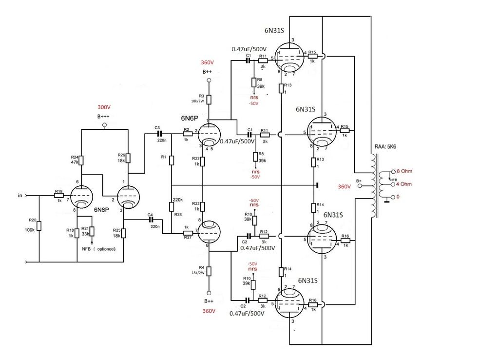
OPT is 5K , not 5k6 , can also be configured for 2k5 . Cathode bias to be adjusted to 50ma .
Ok .... here's my bastardization of the MonoBill . I haven't learnt to use spice , so I re-drew it using MS paint .
Please take a look and let me know what you think , and if it could work . I've halved G1 capacitor values , and doubled resistor values , have reduced B++ from 400V to 360V and reduced B++ resistors from 47k to 18k .
OPT is 5K , not 5k6 , can also be configured for 2k5 . Cathode bias to be adjusted to 50ma .
Last edited:
Sorry about late reply
Sorry for only posting now , for some reason I stopped getting notifications of replies and only noticed all the replies now . Gotta catch up !
I got some parts yesterday and have decided to build a voltage multiplier circuit with the 400VA toroidals I have , instead of using the transformer I posted earlier ( the 6P31S's can't handle the high voltage anyway ) .
The exercise of building this amp is more educational than anything else , thus my not wanting to mod any of the existing amps . I think it's a good challenge to try and design a valve amp that has the ability to drive different loads ( on a domestic level and within reason ) with relative ease .
Some points to consider:
- how much AC voltage needed to drive the output tubes to full power?
- what input sensitivity are you aiming for (separate preamp)?
- how much gain is the input/driver stage providing?
When you want application of gNFB to be optional the circuit is not so well designed IMO.
- how much AC voltage needed to drive the output tubes to full power?
- what input sensitivity are you aiming for (separate preamp)?
- how much gain is the input/driver stage providing?
When you want application of gNFB to be optional the circuit is not so well designed IMO.
Last edited by a moderator:
Like Pieter said, GNF is mandatory to prevent oscillation of the circuit with proper bandwidth limiters. Don't consider this design without GNF , remember you have a lot of gain in this amp and you want to use it to control a low impedance load by using a good amount of feedback, you will have to do this by ear tuning, unless your a mathematician and can calculate the gain and phase degrees of each stage.
It looks like it is going to be a killer amp.
maybe you already know this , but just a reminder for your parts to buy: the 39K grid bias will be 50K trim-pot of around 1 watt.
The 6n31s cathode resistors are 10R and have each a bias tap point to adjust the amp bias.
One very important thing: the Voltage to 6n6p is 350 V, 6n6p is different from a good quality 6sn7 or 6sl7,
My experience is that 120 to 240 V is the best voltage for that tube, over 260 V and you will get a surprise like noise or premature failure.
Last edited:
- how much AC voltage needed to drive the output tubes to full power?
Perhaps the B+ is still a little high and In should bring it down to 300V or perhaps even 250V ?
- what input sensitivity are you aiming for (separate preamp)?
I'm thinking of just using passive pre ATM .
- how much gain is the input/driver stage providing?
I'm going to have to learn how to calculate that ! 😕
When you want application of gNFB to be optional the circuit is not so well designed IMO.
The reasoning here is to hear what difference it would make . I can also try the various types of feedback suggested in this thread at a later stage and also hear the difference . This circuit is for me to play with , and learn from .
Like Pieter said, GNF is mandatory to prevent oscillation of the circuit with proper bandwidth limiters. Don't consider this design without GNF , remember you have a lot of gain in this amp and you want to use it to control a low impedance load by using a good amount of feedback, you will have to do this by ear tuning, unless your a mathematician and can calculate the gain and phase degrees of each stage.
I used to be pretty good at maths , but don't have sufficient electronics knowledge to even know what calculations to use .
In this case , I'll take the GNFB as a given , and tune by ear trying different value resistors .
It looks like it is going to be a killer amp.
May your words ring true . 🙂
Maybe you already know this , but just a reminder for your parts to buy: the 39K grid bias will be 50K trim-pot of around 1 watt.
The 6n31s cathode resistors are 10R and have each a bias tap point to adjust the amp bias.
Those are exactly what I bought , those little blue trimpots , thanks for the heads-up ! My knowledge is pretty lacking , to say the least .
One very important thing: the Voltage to 6n6p is 350 V, 6n6p is different from a good quality 6sn7 or 6sl7,
My experience is that 120 to 240 V is the best voltage for that tube, over 260 V and you will get a surprise like noise or premature failure.
So maybe increase the 18k to 33k ?
Also , do you think I should go for a lower B+ , and lower B++ ? All 300V ?
Thanks for the help gabdx !
One very important thing: the Voltage to 6n6p is 350 V, 6n6p is different from a good quality 6sn7 or 6sl7,
My experience is that 120 to 240 V is the best voltage for that tube, over 260 V and you will get a surprise like noise or premature failure.
That's not correct: there are anode and cathode resistors with voltage drop because of DC current.
When supplying the driver stage with the same 300V as the input stage both 6N6 tubes will feel fine and work within their limits.
That's not correct: there are anode and cathode resistors with voltage drop because of DC current.
When supplying the driver stage with the same 300V as the input stage both 6N6 tubes will feel fine.
Hi Pieter
I will adjust accordingly . Is it OK to take 300V to driver and input tubes from the same point ?
Thank you !
Ari
PS : fredeb = bederf ( in Afrikaans or Dutch ) = spoilt ( in English ) 🙂 So backwards = unspoilt

Last edited:
I would say it's best to design your circuit to be as linear as possible open loop and then add the negative feedback to make it more linear and lower the output impedance (increase damping factor to the speaker). It's not good practice to design an easily distorted audio circuit and then lean on the NFB crutch to make it perform acceptably.
Do you mean Ebb (B++) or Vp (voltage at the plate/anode)? Since 6N6P is often run at a plate voltage of about 160V with a plate load resistor of about 10k to 15k ohms, it will often see a B+ feed of >300V. I don't see what's wrong with that. I have a single-ended line preamp using 6N6P with B+ of over 400V and a 15k plate load resistor, running each 6N6P triode at nearly 20mA Ip. It just goes and goes, no issues for years.
The thing about 6N6P is that it's less similar to a 6SN7 type of tube (and nothing at all like a 6SL7), but very similar to a 5687. It likes high current/low voltage. It has much lower internal plate resistance than a 6SN7 (6N6P will be around 2.5k, while 6SN7 will be around 9k) and higher transconductance, for similar gain (mu or amplification factor).
From working with this tube long-term, a 350V supply is fine for 6N6P, but it will work best if the plate current through each of its triodes is in the vicinity of 15mA. The way the proposed design is set up, you're using the 6N6P tubes like 6SN7 tubes were used in the original Williamson amp -- that is, with high value plate load resistors and low plate currents. This maximizes gain, but is not so great for linearity.
What if you used your 6N6P tubes with more like 10mA plate current each? R24 would be 15k ohms, aiming for 150V on the first stage plate, and about 7V on its cathode ('center-biased'). The second stage cathodyne (concertina) phase splitter would need plate and cathode load resistors of about 7.5k. You would try to adjust the value of R18 to get equal plate current through both triodes of the first 6N6P (input stage and cathodyne phase splitter stage). My initial guess from looking at the plate curves is that R18 would be about 700 ohms (680 would be the closest standard value).
The differential (push pull) driver stage is already pretty close to where I'd put it. For Ebb (B++) of 360V, center-biasing the tube with Rp = 18k would give you Ip = 10mA, Vp = 180V, and Vg = 9V. R22 and R23 would be about 910 ohms each, which is pretty close to the 1k that's in there now. You could join the cathodes of the two 6N6P sections and run a single 470R to ground (shared cathode resistor), which would increase the gain of the driver stage (not needed, but it's there if you want it).
The gain of those first two stages would be around 10X or thereabouts. The gain of the differential driver stage would be only about 10X (the lowish gain is due to unbypassed cathode resistors). So to get your 50V peak input to the output 6P31S's, an input signal of about 500mV peak should get you to full power output. if you want to make it so that a 2V peak signal drives the amp to full power, you could apply 4X global negative feedback (12dB).
As you go to larger value plate resistors, you start to operate the 6N6P tubes in a more 'starved' condition, where they'll give you more gain (which you don't need in this circuit) and more harmonic distortion.
Sorry for the interruption. Please carry on.
--
One very important thing: the Voltage to 6n6p is 350 V, 6n6p is different from a good quality 6sn7 or 6sl7,
My experience is that 120 to 240 V is the best voltage for that tube, over 260 V and you will get a surprise like noise or premature failure.
Do you mean Ebb (B++) or Vp (voltage at the plate/anode)? Since 6N6P is often run at a plate voltage of about 160V with a plate load resistor of about 10k to 15k ohms, it will often see a B+ feed of >300V. I don't see what's wrong with that. I have a single-ended line preamp using 6N6P with B+ of over 400V and a 15k plate load resistor, running each 6N6P triode at nearly 20mA Ip. It just goes and goes, no issues for years.
The thing about 6N6P is that it's less similar to a 6SN7 type of tube (and nothing at all like a 6SL7), but very similar to a 5687. It likes high current/low voltage. It has much lower internal plate resistance than a 6SN7 (6N6P will be around 2.5k, while 6SN7 will be around 9k) and higher transconductance, for similar gain (mu or amplification factor).
From working with this tube long-term, a 350V supply is fine for 6N6P, but it will work best if the plate current through each of its triodes is in the vicinity of 15mA. The way the proposed design is set up, you're using the 6N6P tubes like 6SN7 tubes were used in the original Williamson amp -- that is, with high value plate load resistors and low plate currents. This maximizes gain, but is not so great for linearity.
What if you used your 6N6P tubes with more like 10mA plate current each? R24 would be 15k ohms, aiming for 150V on the first stage plate, and about 7V on its cathode ('center-biased'). The second stage cathodyne (concertina) phase splitter would need plate and cathode load resistors of about 7.5k. You would try to adjust the value of R18 to get equal plate current through both triodes of the first 6N6P (input stage and cathodyne phase splitter stage). My initial guess from looking at the plate curves is that R18 would be about 700 ohms (680 would be the closest standard value).
The differential (push pull) driver stage is already pretty close to where I'd put it. For Ebb (B++) of 360V, center-biasing the tube with Rp = 18k would give you Ip = 10mA, Vp = 180V, and Vg = 9V. R22 and R23 would be about 910 ohms each, which is pretty close to the 1k that's in there now. You could join the cathodes of the two 6N6P sections and run a single 470R to ground (shared cathode resistor), which would increase the gain of the driver stage (not needed, but it's there if you want it).
The gain of those first two stages would be around 10X or thereabouts. The gain of the differential driver stage would be only about 10X (the lowish gain is due to unbypassed cathode resistors). So to get your 50V peak input to the output 6P31S's, an input signal of about 500mV peak should get you to full power output. if you want to make it so that a 2V peak signal drives the amp to full power, you could apply 4X global negative feedback (12dB).
So maybe increase the 18k to 33k ?
As you go to larger value plate resistors, you start to operate the 6N6P tubes in a more 'starved' condition, where they'll give you more gain (which you don't need in this circuit) and more harmonic distortion.
Sorry for the interruption. Please carry on.
--
Last edited:
So to get your 50V peak input to the output 6P31S's, an input signal of about 500mV peak should get you to full power output.
-50V bias does not seem to be correct for 6P31S; left from the other circuit?
Good catch!! Yes, from looking at its data sheet (http://tubedata.milbert.com/sheets/113/6/6P31S.pdf) 6P31S with 360V on its plate would normally have about -25V grid-cathode bias.
So, even less reason to design the phase splitter and driver stages for maximum gain. Design for best linearity/least distortion, and it looks like you'll have plenty of gain for NFB no matter what you do.
BTW, that's a Williamson-style phase splitter/driver circuit in this design. Because of the multiple gain stages, it will have quite a lot of gain. The original Williamson design was made that way so that 20dB NFB could be applied around the whole amp, from speaker terminal to input stage cathode. Because the NFB loop went around both the output transformer and four vacuum tube stages, it required a specially designed output transformer, yet was still prone to instability (oscillations, 'motorboating') when that much NFB was applied.
The proposed circuit should be fine if used with lesser output transformers and 10dB or less of NFB, in which case you need less gain than was used in the original circuit. Of course, if you use less NFB, you need to make sure the driver stages are more linear. Also, you'll wind up with a higher output impedance from your amplifier (lower damping factor) which will give you that 'tube-y' bass response (looser, less tight, possibly a slight bass boost).
Every part of a circuit you 'improve' exacts a penalty on another part of the circuit's performance. The challenge of designing a good circuit is to strike a pleasing balance between all the various compromises. That makes it all too easy to fall into 'analysis paralysis.' (Ask me how I know...)
--
Last edited:
Those 6P31 data are for Vg2=170V ! Here, with UL, it's much higher and -50V is possibly even to little.
This is what I make of it with some small changes.
If you use the same V+ for both stages there is more risk of motorboating (feedback on the powerline).
Mona
This is what I make of it with some small changes.
If you use the same V+ for both stages there is more risk of motorboating (feedback on the powerline).
Mona
Attachments
I would say it's best to design your circuit to be as linear as possible open loop and then add the negative feedback to make it more linear and lower the output impedance (increase damping factor to the speaker). It's not good practice to design an easily distorted audio circuit and then lean on the NFB crutch to make it perform acceptably.
That makes a whole lot of sense - right from the start then ! Tweaks to be applied later , so as to notice the difference .
Do you mean Ebb (B++) or Vp (voltage at the plate/anode)? Since 6N6P is often run at a plate voltage of about 160V with a plate load resistor of about 10k to 15k ohms, it will often see a B+ feed of >300V. I don't see what's wrong with that. I have a single-ended line preamp using 6N6P with B+ of over 400V and a 15k plate load resistor, running each 6N6P triode at nearly 20mA Ip. It just goes and goes, no issues for years.
This is re-assuring . Somewhere else I was advised to get the get the voltage at the input stage anode ( after voltage drop resistor ) to between 85 and 95V . Can you see any sense in that ? Increased current ?
The thing about 6N6P is that it's less similar to a 6SN7 type of tube (and nothing at all like a 6SL7), but very similar to a 5687. It likes high current/low voltage. It has much lower internal plate resistance than a 6SN7 (6N6P will be around 2.5k, while 6SN7 will be around 9k) and higher transconductance, for similar gain (mu or amplification factor).
Your state ment here seems to re-inforce my previous statement re 85-95V .
From working with this tube long-term, a 350V supply is fine for 6N6P, but it will work best if the plate current through each of its triodes is in the vicinity of 15mA. The way the proposed design is set up, you're using the 6N6P tubes like 6SN7 tubes were used in the original Williamson amp -- that is, with high value plate load resistors and low plate currents. This maximizes gain, but is not so great for linearity.
Again the lower B++ ( 300V instead of 360V driver tubes ) seems wise then .
What if you used your 6N6P tubes with more like 10mA plate current each? R24 would be 15k ohms, aiming for 150V on the first stage plate, and about 7V on its cathode ('center-biased'). The second stage cathodyne (concertina) phase splitter would need plate and cathode load resistors of about 7.5k. You would try to adjust the value of R18 to get equal plate current through both triodes of the first 6N6P (input stage and cathodyne phase splitter stage). My initial guess from looking at the plate curves is that R18 would be about 700 ohms (680 would be the closest standard value).
I'm starting to think I should draw up another version of the circuit using your suggestions , alternatively I have some turret boards where I could drop in resistors without soldering them , to see what difference the changes would make . So build an experimental amp , and a type of bench PSU to easily change voltage .
The differential (push pull) driver stage is already pretty close to where I'd put it. For Ebb (B++) of 360V, center-biasing the tube with Rp = 18k would give you Ip = 10mA, Vp = 180V, and Vg = 9V. R22 and R23 would be about 910 ohms each, which is pretty close to the 1k that's in there now. You could join the cathodes of the two 6N6P sections and run a single 470R to ground (shared cathode resistor), which would increase the gain of the driver stage (not needed, but it's there if you want it).
Hmmm .... interesting option - and would automatically balance the cathodes .
The gain of those first two stages would be around 10X or thereabouts. The gain of the differential driver stage would be only about 10X (the lowish gain is due to unbypassed cathode resistors). So to get your 50V peak input to the output 6P31S's, an input signal of about 500mV peak should get you to full power output. if you want to make it so that a 2V peak signal drives the amp to full power, you could apply 4X global negative feedback (12dB).
Is that what it would be with the GNFB resistor as it is ? ( 33K )
As you go to larger value plate resistors, you start to operate the 6N6P tubes in a more 'starved' condition, where they'll give you more gain (which you don't need in this circuit) and more harmonic distortion.
Noted - perhaps then your advice re R24 and R26 should be heeded then . R24 = 15k ; R26 = 7k5 .
Sorry for the interruption. Please carry on.
--
Don't be sorry , I appreciate the input . It's amazing to me that you know at a glance what the effects will be .
Thank you kindly .
- Status
- Not open for further replies.
- Home
- Amplifiers
- Tubes / Valves
- Classic 4 valve PPP circuits