I'm sure he has been working on it.
But the original version came from a post by AJT of a likely MJ article/schematic. Since then some other and older variants have been found too. The basic idea has been around for some time, its in an RCA publication even. I first noticed the linearization possible with it using a curve tracer recently. Some discussions with OldEurope also pre-dated the grid 1 current linearization discovery. ( I suggested it then, but it went un-tried for some time. Almost an accidental discovery later that it worked.)
See this for original Crazy Drive curves:
http://www.diyaudio.com/forums/tube...nificent-television-tubes-47.html#post4574362
And this for 1st (recent) Crazy Drive amplifier by Mickeystan:
http://www.diyaudio.com/forums/tube...nificent-television-tubes-67.html#post4675483
Older schematics found:
Attachments
Last edited:
Given the low HF response of the Hammond 1650R, the amount of gNFB is likely to be limited, so lNFB will be needed to get the output impedance down to an acceptable level, especially if fredeb wants to drive difficult loads. Of course, by doing so, the design is drifting away from the classic designs of yore.
I'm sure he has been working on it.
But the original version came from a post by AJT of a likely MJ article/schematic. Since then some other and older variants have been found too. The basic idea has been around for some time, its in an RCA publication even. I first noticed the linearization possible with it using a curve tracer recently. Some discussions with OldEurope also pre-dated the grid 1 current linearization discovery. ( I suggested it then, but it went un-tried for some time. Almost an accidental discovery later that it worked.)
See this for original Crazy Drive curves:
http://www.diyaudio.com/forums/tube...nificent-television-tubes-47.html#post4574362
And this for 1st (recent) Crazy Drive amplifier by Mickeystan:
http://www.diyaudio.com/forums/tube...nificent-television-tubes-67.html#post4675483
Older schematics found:
Very interesting concept - so , one effectively the physical surface area of g1 = g1 + g2 , having more influence on electrons passing . I guess Mickystan is busy experimenting on his build . I wonder what it sounds like ? It appears he has a good set of speakers attached .
It's crazy , you testing all those valves , you must be learning so much !
Given the low HF response of the Hammond 1650R, the amount of gNFB is likely to be limited, so lNFB will be needed to get the output impedance down to an acceptable level, especially if fredeb wants to drive difficult loads. Of course, by doing so, the design is drifting away from the classic designs of yore.
I was just looking recently at some thread with INFB , re-inforcement throughout . It's amazing how poetic circuit design can be , I'm still trying to figure out how PSU design resonates with the rest of the circuit , compared to designing PSU with large capacitance for " clean " reserve power .
Last edited:
re: Jazbo8
"so lNFB will be needed to get the output impedance down to an acceptable level, especially if fredeb wants to drive difficult loads. Of course, by doing so, the design is drifting away from the classic designs of yore."
I think that sums up the problem here. Classic designs typically used all global N Fdbk, since speakers were tube friendly at the time. Some CFB designs, like the Mac, AR and similar amps (that LW6 amp), could handle a difficult speaker, but require special custom (and expensive) OTs to make them.
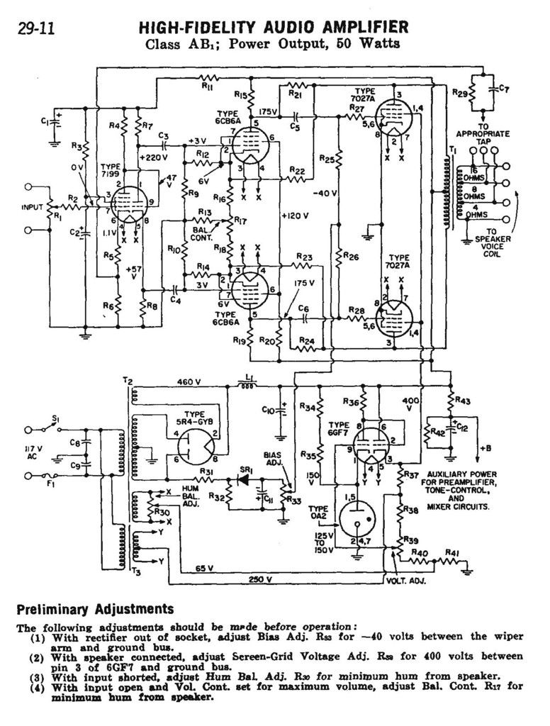
On the other hand, it is not that difficult to make a "local" N Fdbk amplifier using R feedbacks to a driver stage using a conventional OT. And there are recent designs around like Pete Millett's DCPP amp and variants that are well documented. The HK Citation II is a classic local Fdbk design, a bit more complex. (Thorston Loesch type amps too, using crossed local N Fdbks to the driver stage grids. Or the RCA 50 Watter Amp, with local N Fdbks to the driver stage cathodes. Would need updating for available tubes. See below: )
"so lNFB will be needed to get the output impedance down to an acceptable level, especially if fredeb wants to drive difficult loads. Of course, by doing so, the design is drifting away from the classic designs of yore."
I think that sums up the problem here. Classic designs typically used all global N Fdbk, since speakers were tube friendly at the time. Some CFB designs, like the Mac, AR and similar amps (that LW6 amp), could handle a difficult speaker, but require special custom (and expensive) OTs to make them.
On the other hand, it is not that difficult to make a "local" N Fdbk amplifier using R feedbacks to a driver stage using a conventional OT. And there are recent designs around like Pete Millett's DCPP amp and variants that are well documented. The HK Citation II is a classic local Fdbk design, a bit more complex. (Thorston Loesch type amps too, using crossed local N Fdbks to the driver stage grids. Or the RCA 50 Watter Amp, with local N Fdbks to the driver stage cathodes. Would need updating for available tubes. See below: )
Attachments
Last edited:
Thanks smoking-amp ! I also am busy reading this :http://www.clarisonus.com/Archives/TubeTheory/Schade%201938%20Beam%20Power%20Tubes.pdf
So it appears that rise in impedance at resonant frequency of moving coil loudspeakers interacting with plate to plate impedance of Output tubes cause the bass boom . So the Schade feedback provides damping for these effects .
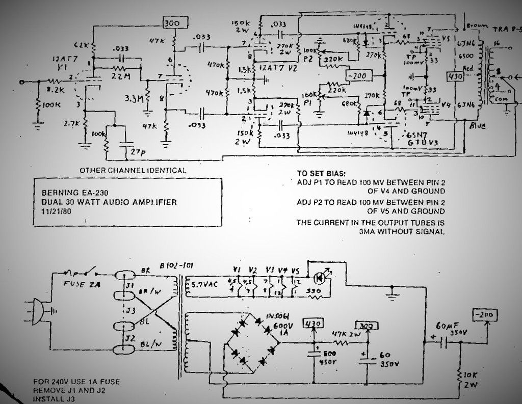
The Berning EA230 appears to make use of Schade feedback , not as extreme as the RCA example .
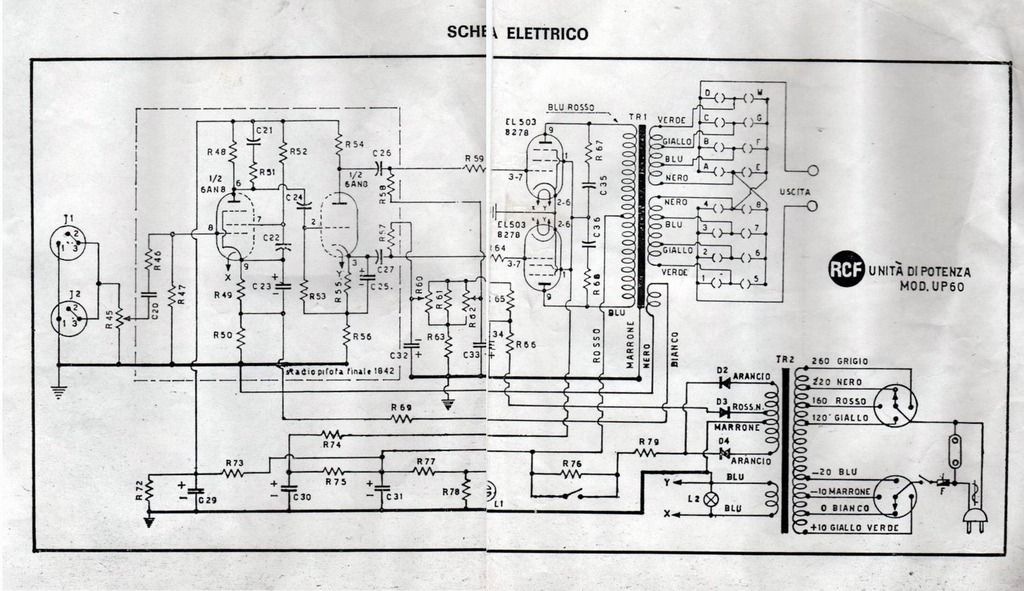
What do you think of the anode-anode de-coupling ( or is it coupling? ) in the RCF UP60 ? Also note the extra secondary winding on OPT for GNFB , quite interesting .
So it appears that rise in impedance at resonant frequency of moving coil loudspeakers interacting with plate to plate impedance of Output tubes cause the bass boom . So the Schade feedback provides damping for these effects .
The Berning EA230 appears to make use of Schade feedback , not as extreme as the RCA example .
What do you think of the anode-anode de-coupling ( or is it coupling? ) in the RCF UP60 ? Also note the extra secondary winding on OPT for GNFB , quite interesting .
There's another wrinkle with that Berning design -- screen drive. The signal from the 6SN7 cathode follower goes to the 6JN6 screen grid, while the 6JN6 suppressor grid and control grid are tied to its cathode.
Another wrinkle is that the plates of both the 6SN7 cathode follower and the 12AT7 LTP (V2) are connected to the main B+, not to the plates of the 6JN6 output tubes. So does that mean there's no 'plate to grid' feedback going on, just the plate to cathode feedback in place from the 6JN6 plates to the 12AT7 (V2) cathodes?
--
Hi Rongon - I'll try and edit it tomorrow morning , or else ask a mod to delete it . I downloaded this from somewhere on the net a while back , and merely adjusted Brightness/Contrast to get it clearer . I could attempt to correct it given the right information .
Looks like the Berning design is only using plate to driver cathode local Fdbks. (plus global Fdbk) That really is the most tube friendly approach. NO low Z summing point to drive, as occurs in resistive Fdbk to the driver plate (ie,"Schade") mode. Tubes will like the high Z load and voltage gain mode for linearity. [ the Berning design could be converted to a "Crazy Drive" scheme easily ]
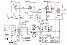
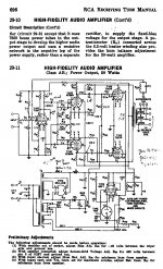
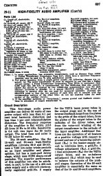
The RCA 50 Watter is really the odd-ball amp. Using BOTH type of local Fdbks to the driver cathodes and driver plates. (plus global) The Fdbk to the driver cathodes makes the driver cathode degeneration R look much higher in value, without disturbing DC conditions. That in turn makes the driver pentode look like a clean (linear) current source for the "Schade" Fdbk up top at the plates. It's a cleverly optimised Schade type Fdbk design, although there is real driver cathode Fdbk as well (greater grid drive to driver tube required, could call it a nested Fdbk design). It is a little mysterious however as to why they would not just use the driver cathode Fdbk paths alone, since the loop gain could be greatly increased without the low Z summing at the driver plates. Maybe someone has an opinion on this? Stability? HF response?
The RCF amp with output plate to plate RC networks uses them for snubber duty, to eliminate HF resonances in the OT. The separate OT Fdbk winding is typically used so that the Fdbk pickoff does not need changing with different output Z taps being used for various speakers (notice the movable global Fdbk required in the RCA without the extra winding), and may allow for paralleling amplifiers.
Last edited:
At this point , wallet not-withstanding 😛 , I won't be buying any transformers . I have a pair of new Hammond 1650r's that I managed to buy in South Africa at a reduced price , I think because they were just lying in a stock room for so long - unwanted .

So - not the " easy to wire " 1650RA " new improved " version .
I guess it's a pity that bandwidth only starts at 30Hz , but this is what I have .
Question : Can I halve impedances and use 5K primary as 2.5k primary ; and 8 and 16 secondaries as 4 and 8 ?
And .... Any thoughts on above mentioned OPT's ?
I built a kt88 , kt77 and kt120 (not quad) with the 1650r.
If you want more power go with kt150, and ultralinear, the transformer sounds bad in triode mode.
it goes way down 1hz , 30 hz is the specification for a -3db at 100 watts, which I doubt you will use, (maybe 15 watts max !, so get that figure to like -3db at 10hz, 15 watts...
this is my last post to reconsider going parallel in big tubes: grid bias is nearly impossible unless going with control pcb boards. Lot more current to drive the tube to their potential and bigger power transformer, more HT current and the inevitable loss of clarity due to tube plates difference.
Hi Rongon - I'll try and edit it tomorrow morning , or else ask a mod to delete it . I downloaded this from somewhere on the net a while back , and merely adjusted Brightness/Contrast to get it clearer . I could attempt to correct it given the right information .
The pictures look fine to me. I'm not sure if you thought I was using the word "wrinkle" in the physical sense (as in a wrinkle in the drawing made it hard to read). I meant 'wrinkle' in a rhetorical sense, as in 'something unexpected and different.' Sorry if I confused matters.
--
Looks like the Berning design is only using plate to driver cathode local Fdbks. (plus global Fdbk) That really is the most tube friendly approach. NO low Z summing point to drive, as occurs in resistive Fdbk to the driver plate (ie,"Schade") mode. Tubes will like the high Z load and voltage gain mode for linearity. [ the Berning design could be converted to a "Crazy Drive" scheme easily ]
I mailed David Berning , and except for the obvious fumbling on G1/2/3 of OT's , the schematic is correct . This is quite a well regarded design , and can probably also be regarded as classic .
The RCA 50 Watter is really the odd-ball amp. Using BOTH type of local Fdbks to the driver cathodes and driver plates. (plus global) The Fdbk to the driver cathodes makes the driver cathode degeneration R look much higher in value, without disturbing DC conditions. That in turn makes the driver pentode look like a clean (linear) current source for the "Schade" Fdbk up top at the plates. It's a cleverly optimised Schade type Fdbk design, although there is real driver cathode Fdbk as well (greater grid drive to driver tube required, could call it a nested Fdbk design). It is a little mysterious however as to why they would not just use the driver cathode Fdbk paths alone, since the loop gain could be greatly increased without the low Z summing at the driver plates. Maybe someone has an opinion on this? Stability? HF response?
I found some more legible copies of the RCA 50 watter and description .
An externally hosted image should be here but it was not working when we last tested it.
An externally hosted image should be here but it was not working when we last tested it.
The RCF amp with output plate to plate RC networks uses them for snubber duty, to eliminate HF resonances in the OT. The separate OT Fdbk winding is typically used so that the Fdbk pickoff does not need changing with different output Z taps being used for various speakers (notice the movable global Fdbk required in the RCA without the extra winding), and may allow for paralleling amplifiers.
What is the extra bit of circuit coming from the shield of the OPT on the RCF amp ? First time I've seen that . I have a pair of these transformers too , maybe worth trying a little later on in my learning curve .
Thank you for all the explanations smoking-amp , you obviously know what you're talking about , and it is very kind of you to care to explain .
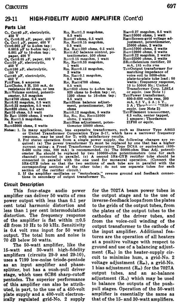
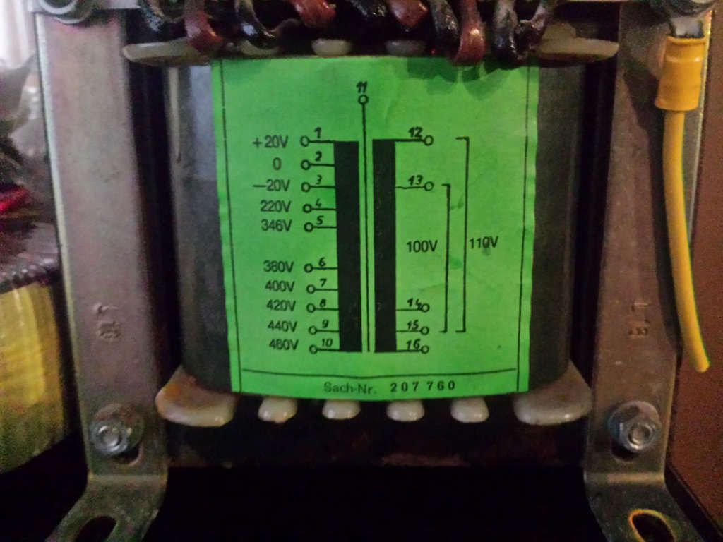
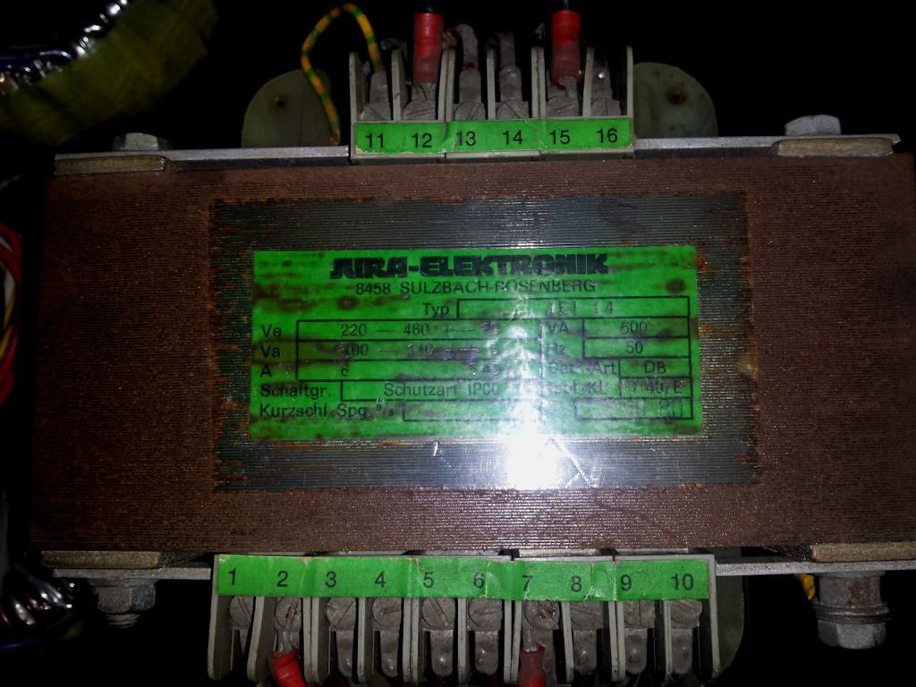
I may have a power transformer , although I'll have to use it with a step-down 240V to 120V first . The step down I have is rated at 100W . The Power Transformer is a 600W beast . Will this be OK for a bit of 1 channel PPP experimenting with the 4x 6P31S and 2x 6N6P ? I have all the correct sockets , suppressor caps etc. I have so 6V transformers to use for filaments .
An externally hosted image should be here but it was not working when we last tested it.
An externally hosted image should be here but it was not working when we last tested it.
Last edited:
I built a kt88 , kt77 and kt120 (not quad) with the 1650r.
If you want more power go with kt150, and ultralinear, the transformer sounds bad in triode mode.
it goes way down 1hz , 30 hz is the specification for a -3db at 100 watts, which I doubt you will use, (maybe 15 watts max !, so get that figure to like -3db at 10hz, 15 watts...
Thanks for the info !
this is my last post to reconsider going parallel in big tubes: grid bias is nearly impossible unless going with control pcb boards. Lot more current to drive the tube to their potential and bigger power transformer, more HT current and the inevitable loss of clarity due to tube plates difference.
I just want to see how it is - I've got those 6P31S's , and they were cheap , in my mind the ideal PP scenario would also have only 2 tubes .
The pictures look fine to me. I'm not sure if you thought I was using the word "wrinkle" in the physical sense (as in a wrinkle in the drawing made it hard to read). I meant 'wrinkle' in a rhetorical sense, as in 'something unexpected and different.' Sorry if I confused matters.
--
No problem rongon , I misunderstood you , too late at night at the time . 🙂
Here's my take on a local-feedback amp with a Hammond 1650R: http://www.diyaudio.com/forums/tubes-valves/248376-amp-kt88-push-pull-shunt-feedback-output-via-p-channel-fet.html
SpreadSpectrum... a crazy build , I will never ever build one 🙂
Good luck on the el36 russian bastards, it is a ''hit or miss'' with russians
(ps. they are ugly tubes!)
(trying to wrap it all many ideas in one post!,
My little experience with 6n6p, horrible drivers, boring sound, however as power tube ppp can be done but it is quite hard and a real difficulty to match to speakers, very fussy tubes.
The 6BL7 or 6BX is a way better and easier tube to use in PPP, at the expense of a very high current power supply, as much as a (basic) kt88 amp. However it will sound better that any pentode strapped in triode with inherent low distortion. Just don't dream to lunch the shuttle in space with it's limited usable power of around 15 watts in PPP
Last edited:
SpreadSpectrum... a crazy build , I will never ever build one 🙂
Good luck on the el36 russian bastards, it is a ''hit or miss'' with russians
(ps. they are ugly tubes!)
(trying to wrap it all many ideas in one post!,
My little experience with 6n6p, horrible drivers, boring sound, however as power tube ppp can be done but it is quite hard and a real difficulty to match to speakers, very fussy tubes.
The 6BL7 or 6BX is a way better and easier tube to use in PPP, at the expense of a very high current power supply, as much as a (basic) kt88 amp. However it will sound better that any pentode strapped in triode with inherent low distortion. Just don't dream to lunch the shuttle in space with it's limited usable power of around 15 watts in PPP
I really like the sound of E182CC's as drivers in my 300B PP amp ( compared to the sound of various 5687's that were in there before ) . The 6N6P is often compared to the E182CC , and they're cheap , thus my choice . The E182CC's also had the most well defined bass rendering in the 300B PP , where the various 5687's I tried were boomy . The "earthable" shield between 2 sections of 6N6P is also a pleasant feature .
As far as the 6BL7 or 6 BX are concerned , I may give them a try if I come across them , but I think my mind is made up to try the 6P31S's .
(ps. they are ugly tubes!)

Here's my take on a local-feedback amp with a Hammond 1650R: http://www.diyaudio.com/forums/tubes-valves/248376-amp-kt88-push-pull-shunt-feedback-output-via-p-channel-fet.html
Wow ! Beautiful work . Lucky brother indeed - what a Xmas present .
"What is the extra bit of circuit coming from the shield of the OPT on the RCF amp ? "
Probably just showing that the magnetic core is grounded to the chassis (via mounting bolts typically).
----
"My little experience with 6n6p, horrible drivers, boring sound..."
Well the curves look fairly constant Mu, maybe lacking 2nd harmonic warmth.
http://klausmobile.narod.ru/td/data/_6n6p.GIF
--
"(ps. they are ugly tubes!)"
Use some incandescent resistors in the power supply. Or compactron TV Sweep tubes with an LED or three in the socket.
-
Attachments
Last edited:
Hey smoking-amp
Do you think that 600VA power transformer will work with the 100W stepdown ? ( that I posted a few posts back )
Look again - It looks like the bias supply is grounded there , probably an error .
Maybe in time I'll also get to understand seeing the 2nd harmonic warmth bit from looking at the curves .
 DISCO
DISCO

Do you think that 600VA power transformer will work with the 100W stepdown ? ( that I posted a few posts back )
"What is the extra bit of circuit coming from the shield of the OPT on the RCF amp ? "
Probably just showing that the magnetic core is grounded to the chassis (via mounting bolts typically).-
Look again - It looks like the bias supply is grounded there , probably an error .
"My little experience with 6n6p, horrible drivers, boring sound..."
Well the curves look fairly constant Mu, maybe lacking 2nd harmonic warmth.
http://klausmobile.narod.ru/td/data/_6n6p.GIF-
Maybe in time I'll also get to understand seeing the 2nd harmonic warmth bit from looking at the curves .
"(ps. they are ugly tubes!)"
Use some incandescent resistors in the power supply. Or compactron TV Sweep tubes with LEDs in the socket.
DISCO
 DISCO
DISCOWith cheap enough output tubes, one could go for "Flash and Awe" effects, just run the tubes at 3X their ratings. Automatic signal switchover to the next parallel banked tube. Consult George on how to do this.
Attachments

Last edited:
- Status
- Not open for further replies.
- Home
- Amplifiers
- Tubes / Valves
- Classic 4 valve PPP circuits