I've been looking at classic Push Pull circuits in order to gain an understanding of PP valve amplifiers . Circuits I've been looking at are for example :
1. Williamson 50W amplifier ( KT88 PP )
2. Mullard 5-20 ( EL34 PP ) , and consequently ...
3. Claus Byrith 4-30 ( EL34 PP ) - seems to be a proven design by now
And many more that I've been able to find on the net .
I'm a complete valve noob ( although 46 years old ) and have only recently become interested in valve circuits . I've assembled some Class AB and D solid state amps you can buy as modules or kits containing all components . This doesn't require much electronic knowledge , and possibly the most complex thing I've done is design my own dual rail PSU to power 200-250W amplifier modules .
So .... after looking at various valve circuits for months now , I think I'm finally beginning to gain an understanding of how PP valve amplifiers work , the Byrith article written for Lundahl helped a lot . Keeping things straight-forward and simple to one such as I .
Old-fasioned 30W Push-Pull amplifier ⋆ Lundahl Transformers
What I'd like to ask those who know on this forum is for examples of classic PPP circuits that are proven designs , and that are as simple as the circuits I've mentioned above . Nothing with solid state current regulation ( I'd rather get into that later , when I have a complete understanding of basic designs ) .
Any of the circuits that you referenced could be turned into PPP by adding more output tubes, just make sure to order the correct output transformers, i.e., 1/x of the primary plate-to-plate impedance, and multiply by x the output power rating, where x is the number of output tube pairs.
Any of the circuits that you referenced could be turned into PPP by adding more output tubes, just make sure to order the correct output transformers, i.e., 1/x of the primary plate-to-plate impedance, and multiply by x the output power rating, where x is the number of output tube pairs.
If one had to double the amount of output tubes , would you halve the plate to plate impedance ?
Would drive requirements from the driver stage remain the same ?
Here's an interesting thread : Tube DIY Asylum
Similarly to the OP in that thread , my aim would be to build a valve amplifier that has the ability to drive difficult loads ( ie. 2 or 3-way speakers that are not efficient , say ... rated at 8 ohm with impedance dips down to 3 or 2 ohm ) ; and that has a high damping factor , for a valve amp .
An externally hosted image should be here but it was not working when we last tested it.
This one looks simple and promessing.
Mona
Would this work ? Does it need input stage added ?
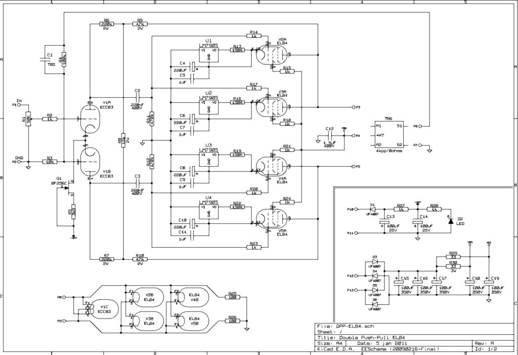
Just Ohm's law, if the plate resistance drops by half, then the primary impedance drops by half as well. The drive requirement remains the same, of course, for a peace of mind, you could add some cathode followers after the PI to beef up the drive capability, but they are usually not needed.
For driving very low impedance loads, e.g., 2~3 Ohm on the 8 Ohm tap, very few tube amplifiers could stand such abuse for long period of time, although for normal or modest listening level with music (i.e., not continuous sine wave) you may be ok, even if the distortion might be quite high.
For driving very low impedance loads, e.g., 2~3 Ohm on the 8 Ohm tap, very few tube amplifiers could stand such abuse for long period of time, although for normal or modest listening level with music (i.e., not continuous sine wave) you may be ok, even if the distortion might be quite high.
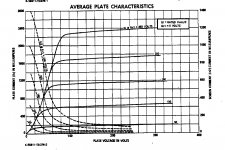
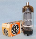
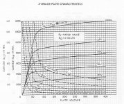
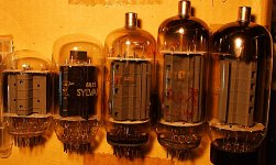
To drive a difficult load, why parallel a bunch of wimpy expensive tubes that will need matching? Just use a tube that can do the job:
26DQ5 $3
6HJ5 $4
21LG6 $4
6CB5A $5
36LW6 $11
26DQ5 $3
6HJ5 $4
21LG6 $4
6CB5A $5
36LW6 $11
Attachments
Would this work ? Does it need input stage added ?
An externally hosted image should be here but it was not working when we last tested it.
Depends how sensitive you want the input, here you have about 1.5V input.
I have to agre with Smoking-amp, bigger tubes are better then double ones.
Mona
I've been looking at classic Push Pull circuits in order to gain an understanding of PP valve amplifiers . Circuits I've been looking at are for example :
1. Williamson 50W amplifier ( KT88 PP )
2. Mullard 5-20 ( EL34 PP ) , and consequently ...
3. Claus Byrith 4-30 ( EL34 PP ) - seems to be a proven design by now
And many more that I've been able to find on the net .
I'm a complete valve noob ( although 46 years old ) and have only recently become interested in valve circuits . I've assembled some Class AB and D solid state amps you can buy as modules or kits containing all components . This doesn't require much electronic knowledge , and possibly the most complex thing I've done is design my own dual rail PSU to power 200-250W amplifier modules .
So .... after looking at various valve circuits for months now , I think I'm finally beginning to gain an understanding of how PP valve amplifiers work , the Byrith article written for Lundahl helped a lot . Keeping things straight-forward and simple to one such as I .
Old-fasioned 30W Push-Pull amplifier ⋆ Lundahl Transformers
What I'd like to ask those who know on this forum is for examples of classic PPP circuits that are proven designs , and that are as simple as the circuits I've mentioned above . Nothing with solid state current regulation ( I'd rather get into that later , when I have a complete understanding of basic designs ) .
You better use bigger bottles than let say 4 X el34.
You gain nothing in output impedance by parallel tubes, the only reason to parallel tubes is to boost the power of low impedance wimpy tubes.
If you need that much power use two x KT150, you will get better sound
To drive a difficult load, why parallel a bunch of wimpy expensive tubes that will need matching? Just use a tube that can do the job:
26DQ5 $3
6HJ5 $4
21LG6 $4
6CB5A $5
36LW6 $11
Indeed - in fact I have 8x Svet 6P31S ( EL36 equivalents ) that I scored for $33 incl. shipping , 2 pairs of matched quads . I have a bunch of 6N6P's and 6N2P's that I also got for really good prices . I have a pair of Hammond 1650r 100W transformers . I don't have a power transformer , unless I can do voltage multiplier on 2x 400VA 35-0-35 5a , 15-0 3A , 15-0 1A toroidal transformers .
The primaries were wound for 220V , but local supply is 240V , so secondaries result in 43-0-43 , 2x 18-0 . They are 5kg beasts , I use them on Solid State amps requiring 60-0-60 VDC . They run quiet and cool , got them on the cheap too .
Just Ohm's law, if the plate resistance drops by half, then the primary impedance drops by half as well. The drive requirement remains the same, of course, for a peace of mind, you could add some cathode followers after the PI to beef up the drive capability, but they are usually not needed.
For driving very low impedance loads, e.g., 2~3 Ohm on the 8 Ohm tap, very few tube amplifiers could stand such abuse for long period of time, although for normal or modest listening level with music (i.e., not continuous sine wave) you may be ok, even if the distortion might be quite high.
Hi Jazbo8
You have been a part of most of the threads I have perused on this forum - thank you for all your valuable input .
Do you know of valve designs that would withstand this kind of abuse ?
What's PI ? 😱
As far as going from a low load to higher goes ( I'm not sure if it counts between stages of valve amp ) ; Would one want to change the G1 grid stoppers so as to raise input impedance of output valves in such a scenario ?
a lower impedance load wont do any harm to your bottles
you might lose some bass material but not critical
Any valve design can withstand low impedance of say 2 ohm if you use enough feedback/gain and raise the transformer impedance ratio recommended for your tubes, again, // bottles does nothing to help
You have no idea how an amplifier works, G1 grid stoppers counter oscillation and have nothing to do with the tube grid input resistance...
You're right , I'm learning .... found this though :
http://www.diyaudio.com/forums/tubes-valves/111058-please-explain-grid-stoppers.html
So I guess the grid stoppers stabilize incoming current that could cause instability in the valve , which could cause voltage swings , which could cause oscillation ? Is that right ?
noooo they don't touch the current,
they create a filter with the grid capacitance to limit the high frequency of the amplifier, as long as you keep it to around 350khz (it is more complicated, look at Morgan Jones book) minimum for each stage the amplifier should sound fine.
It is a simple low pass first order filter calculated with the tube G1 specified capacitance
You can built your whole amp without any grid resistors and it will be fine but may catch a radio signal and play music or cook your tweeter slowly, the output transformer acts as a protector for your speakers from the high frequency, placing a resistance and a filter will also protect from Ghz and Mhz interference, good thing to place parallel to the amp output in bottle amps!
Last edited:
noooo they don't touch the current,
they create a filter with the grid capacitance to limit the high frequency of the amplifier, as long as you keep it to around 350khz (it is more complicated, look at Morgan Jones book) minimum for each stage the amplifier should sound fine.
It is a simple low pass first order filter calculated with the tube G1 specified capacitance
You can built your whole amp without any grid resistors and it will be fine but may catch a radio signal and play music or cook your tweeter slowly, the output transformer acts as a protector for your speakers from the high frequency, placing a resistance and a filter will also protect from Ghz and Mhz interference, good thing to place parallel to the amp output in bottle amps!
Ah ! A low pass filter for the signal , thanks for making that plain me , I understand now . I'll take a look at the Morgan Jones book too . Thanks gabdx !
Edit : I just checked out your amps at your website - The PPP 6N6P looks very interesting - How do you like the sound of that compared to your more powerful amps ?
Last edited:
Some clarification maybe needed.
Pentode outputs (without N Fdbk) are high output impedance, so paralleling more will not help with final Rp alone. Adding a N Fdbk loop will lower the output impedance. However, the tubes/OT combo must be able to deliver the current commanded by the N Fdbk. So more tubes, or a bigger tube, CAN help meet the requirements.
I would take the lowest speaker impedance expected, at the highest power required (for bass boom say), and figure the peak speaker current required. Then work that backwards through the OT 1/turns ratio to get the peak current required from the tube(s). A higher primary Z OT will require less peak current from the tube(s), but may push you to a higher B+ voltage than desired, to meet the maximum (peak) power spec. (max. avg. power will be 1/2 that) I would stay below +450V B+ for reasonable economy of the power supply. (and also stay within the spec for the tube screen grid voltage for max knee current) A bigger tube or parallel tubes may solve any shortcoming on current. You have to play with the numbers for various tube and OT scenarios until a happy combo develops that meets the peak current requirement and the Watts output target.
Then you need to figure how much the native Rp of the tube(s) needs to be lowered to be less than the reflected Z of the speaker through the OT (determining speaker damping factor). That ratio will tell you how much N Fdbk loop gain is needed in the front end (the minimum). Could be global N Fdbk, or some form of "local" (non OT inclusive) N Fdbk.
6P36C looks to be rated 550 mA max peak for +170V on the screen grid.
6P45S/6KG6/EL509 1250 mA peak for +160V Vg2
36LW6 1400 mA peak for +180 Vg2
35LR6 1300 mA peak for +160 Vg2
21LG6 900 mA for +175 Vg2
26DQ5 870 mA peak for +175 Vg2
6HJ5 750 mA peak for +175 VG2
21HB5A 700 mA peak for +175 Vg2
6CB5A 540 mA peak for +175 Vg2
EL84 160 mA peak for +300 Vg2
EL34 350 mA peak for +350 Vg2
George (Tubelab) has found that around +150 Vg2 works well for low distortion with the TV sweep tubes (ie, for all of the above list, except EL84 and EL34). That would lower the peak current ratings above by Vg2'/Vg2 to the 1.5 power. (for example: 6P36C: 550mA x (150/170)^1.5 = 456 mA peak at +150 Vg2)
Have fun playing with the numbers! Something will work.
Last edited:
What world do you live in? If lower impedance does no harm, then what is the point of having multiple output tubes?! Were the designers of those amplifiers smoking crack?🙄a lower impedance load wont do any harm to your bottles...
Any valve design can withstand low impedance of say 2 ohm if you use enough feedback/gain and raise the transformer impedance ratio recommended for your tubes, again, // bottles does nothing to help...
Do you know of valve designs that would withstand this kind of abuse?
Off the top of my head, no, but perhaps some of the very large ARC designs could handle such low load without blowing up. Also bear in mind that, it is not easy to find reasonably priced output transformer that has the required primary impedance AND high power handling capability, so be prepared to open your wallet.
There is an article in Glass Audio 3/99 "The LW6-180 Amplifier"
The price of using such tube is that you'll need lower than plate-screen-voltage rating about 250V usually regulated source, but you can easy use solid state regulator (I have this schematic) to reduce the tube count. 6LW6, Class AB2, 2x90W, not sure about 8TU output transformer mentioned.
The price of using such tube is that you'll need lower than plate-screen-voltage rating about 250V usually regulated source, but you can easy use solid state regulator (I have this schematic) to reduce the tube count. 6LW6, Class AB2, 2x90W, not sure about 8TU output transformer mentioned.
- Status
- Not open for further replies.
- Home
- Amplifiers
- Tubes / Valves
- Classic 4 valve PPP circuits
