Wow ! Thank you Mona ! You're going to have to tell me how to plot those graphs sometime . 😉
I'm busy making up voltage quadrupler circuit now . I might need to solder it tomorrow morning because the light is bad in my flat . Once I hook the circuit up we can see exactly what voltage I'm getting . The transformer is putting out 84 to 86VAC , so x4 is 344V , probably slightly less .
Would it be bad form to take B++ 1st , then B+ , then B+++ ; down the line ?

Does the circuit look OK to you ? I will add bigger caps ( and resistors ) afterwards for separate stages .
I'm busy making up voltage quadrupler circuit now . I might need to solder it tomorrow morning because the light is bad in my flat . Once I hook the circuit up we can see exactly what voltage I'm getting . The transformer is putting out 84 to 86VAC , so x4 is 344V , probably slightly less .
Would it be bad form to take B++ 1st , then B+ , then B+++ ; down the line ?
Does the circuit look OK to you ? I will add bigger caps ( and resistors ) afterwards for separate stages .
Last edited:
Getting dark, yes I see, it's winter season at your side.
You will get more than 480V out of that, it's a top-top rectifier.
Once loaded the voltage drops rather dramatically, not for heavy loads like power amps.
You will get more than 480V out of that, it's a top-top rectifier.
Once loaded the voltage drops rather dramatically, not for heavy loads like power amps.
Won't it be 86V x 4 ? The transformer puts out 43-0-43 AC @ 5A , I thought just leaving the centre tap out is OK .
There are 2 more taps .
17V @ 3A : Rectifier to DC for 24VDC Filaments ?
17V @ 1A : Voltage tripler for -50V supply ?
There are 2 more taps .
17V @ 3A : Rectifier to DC for 24VDC Filaments ?
17V @ 1A : Voltage tripler for -50V supply ?
Last edited:
I'll draw up another circuit now . Just to make it clear ( I edited last post to update info ) :
Taps are :
43-0-43 VAC @ 5A
17VAC @ 0.8A ( to be exact )
17VAC @ 3A
I have :
4x Kemet 470uF 450 V ( I was hoping to use only 2 of these for one channel , these big Kemets I imported )
6x 47uF 450V ( easily obtained in South Africa )
12x 10uF 450V ( So hopefully I could use 6 here , but these are easily obtained in South Africa )
4x 47 uF 350V ( easily obtained in South Africa , I thought good for 1st valve @ 300V )
I have a whole lot of 100V , 160V and 250V caps to use for negative bias supply and lower voltage rated caps for DC filament supply .
It's alternating, constantly changing voltage, so what is then 86Vac.No more than the DC voltage value you put on a resistor that develops the same heat.Also named RMS-value or effective value.
If you charge a capacitor via a diode the voltage will go up to the max. voltage within al those fluctuations.
For sine waves the top is the RMS or effective value x √2 (=~1,4x)
Mona
If you charge a capacitor via a diode the voltage will go up to the max. voltage within al those fluctuations.
For sine waves the top is the RMS or effective value x √2 (=~1,4x)
Mona

Well that depends ...
Mona
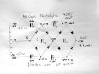
Where you have +120 and +240 next to each other it equals 360 ? ( in 2 positions )
The output in line with ground is full wave , and the 2 on the side are half wave ?
Is there any point to having the cap where you wrote 0V or just leave that one out ?
Is there any point to having the cap where you wrote 0V or just leave that one out ?
I apoligize for my ignorance , you'll be happy to hear I signed up for a free online MIT Practical Electronics course , and have started reading the Morgan Jones " Valve amplifiers " . The guy has an excellent sense of humour and makes things plain in a simple , easy to understand way .Well that depends ...
Mona
Practical Electronics | Edgerton Center | MIT OpenCourseWare
Anyway , I built the multiplier , one stage at a time , because I'm afraid of what I don't know .
There's no load , so I probably have to add one more stage .
Let me know what you think .

Oh ..... and supply is 40-0-40 VAC .
Last edited:
I'm wanting a ~300V B+ , the transformer power rating is 350VA @ 40-0-40 .
What kind of voltage drop should I expect after load ?
http://www.voltagemultipliers.com/html/multcircuit.html
What kind of voltage drop should I expect after load ?
http://www.voltagemultipliers.com/html/multcircuit.html
Last edited:
Hi Parafeed .
Do you have a schematic to have a look at ? Just for comparative purposes . Or a link to your build ?
Good point, a schematic.
Things changed a bit since my original plans so I had to draw it out again 😱
This is as it is playing now.
The EL36s idle at 20mA @ 450V (9W) and can dump 50W into a 4 ohm load (4k4->4 OPT). Screens fixed at 200V (1mA idle, 9mA full).
I let it run for only a minute or so at that output level, but no sign of any redness. More worried for my load resistors than the EL36s.
Attachments
Good point, a schematic.
Things changed a bit since my original plans so I had to draw it out again 😱
This is as it is playing now.
The EL36s idle at 20mA @ 450V (9W) and can dump 50W into a 4 ohm load (4k4->4 OPT). Screens fixed at 200V (1mA idle, 9mA full).
I let it run for only a minute or so at that output level, but no sign of any redness. More worried for my load resistors than the EL36s.
Wow ! Very interesting and unusual setup . Is that a choke on the cathodes of the output tubes ? Are C5 and C6 1uF ? I like the simplicity a lot . I take it that you matched resistors for G1 .
Judging by that 4k7ohm R7 , it looks like a lot of GNFB ! radical amount of power for those EL36's .
I see the 1st valve is 12AT7 , I can't make out what the drivers are . E182CC ?
When you say " no sign of any redness " , do you mean the plates ? From the seriously high B+ ? 🙂
Please post a picture of your amp .
Also , can you give me a comparison of sound quality with other amps you have owned .
What do you think of the 6P31C compared to the EL36 ? Same thing ?
Thank you for sharing .
I was fighting with Eagle to get something that resembles a schematic 😛
The coil under the cathodes of the EL36s is actually part of the OPT. 10% of the primary windings go to each cathode (so 20% of the ac voltage per phase is on the cathode).
That means that the driver must supply that on top of the required g1 drive.
Close to clipping there is 50Vrms on the cathode and 80Vrms on g1.
Considering the -37V on g1, that means it must be going positive a few volts.
The driver can even go further, but the only result of the increase in current is a dramatic sag of my poor power supply. The EL36 really has a lot of current capacity. (Maybe I'll sacrifice a worn out one and see when its anode starts to glow)
C5 and 6 are 1uF indeed.
(G)NFB is 9dB.
Input LTP is the 6201/E81CC (12AT7)
Driver is the E180CC.
I only know the 6P13/6P31 from pictures. It's listed everywhere as an equivalent to the EL36. That's all I know.
The amp isn't finished, but usable 🙄
I want to take it to some friends and get some impressions and opinions.
In direct comparison to my PP triode EL34, I prefer the EL36 amp. It keeps together better when things get loud.
Now that the dust has settled I need to redo the PCBs, clean up the spaghetti and make a new PT. It has only 200VA capacity and gets a bit hot.
Dropping 450V to 200V that jumps between 4mA and 40mA is not the best way to go either. The screens need their own PT winding.
Add a 25V heater winding and I can use the (cheaper) PL36 as well.
Attachments

Last edited:
Alrighty then - I've attached the components to a board now and added one more stage to the multiplier , just in case I need more voltage .

My plan is now to take B+ , B++ and B+++ from here with separate RC filtering . Like so :
B+ ( centre tap of OPT ) - 324V - my thinking is that under load this will drop down to ~300V to 1x 470uF/450V Kemet to 4x 6P31C , 40% tap to G2 dropped to 200V
B++ ( driver tubes ) - 377V to 1x 470uF/450V Kemet to 2 halves of 6N6P via voltage drop Resistor to ~170V
B+++ ( input/splitter) - 271V to 1x47uF ; 96V at input halve of 6N6P after dropper ; and 200V at splitter halve after dropper .
Is there a problem with taking the various voltages from these points , instead of going down the line ? Are the UF4007 diodes noisy ? My thoughts are that some filtering must be taking place in the multiplier already , even though the caps used there are only 4,7uF each .
Bear in mind that PT is 12pound torroidal 350VA on the tap I'm using alone .
Last edited:
Bear in mind that PT is 12pound torroidal 350VA on the tap I'm using alone .
Is this a mono amp? PPP?
I intend building one channel for starters , and once that is sorted I'll copy for 2nd channel . I'm hopping to run both channels from the one supply , sharing the rectifier/multiplier , but having separate components after . And yes , PPP .
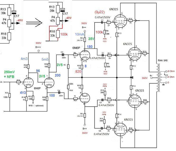
I intend building one channel for starters , and once that is sorted I'll copy for 2nd channel . I'm hopping to run both channels from the one supply , sharing the rectifier/multiplier , but having separate components after . And yes , PPP .
What do you calculate for total HT current draw through 8 output tubes? Total cathode current.
- Status
- Not open for further replies.
- Home
- Amplifiers
- Tubes / Valves
- Classic 4 valve PPP circuits