I'm not familiar with 6N31S. How similar is that to EL37?
http://tubedata.milbert.com/sheets/154/e/EL37.pdf
If similar, then it shows a push-pull arrangement for 350V plate-cathode and screen-cathode, with Vg at -31V.
--
6P31S ( or 6P31C ) is analogous to EL36 , not EL37 .
EL36 @ The Valve Museum
http://www.r-type.org/pdfs/el36.pdf
Agree, Mullard style (which seems have to have the edge over Williamson style in terms of sound quality).
Could be done with 6N6P tubes as well (don't like current poor ECC83 when parallelled output tubes need to be driven).
I actually own a Byrith 4/30 built by JDev on this forum : http://www.diyaudio.com/forums/tubes-valves/12023-mullard-5-20-a-13.html#post707595
It is a fantastic amplifier . I'm into building this PPP though .
I've order some 6J32P to try in place of the EF86's , so I would have a pair to spare then . Maybe for another build .
I also have 6N2P , if one of those would be good in place of either 6N6P , maybe input/phase splitter . Dick van der Merwe opted for these in earlier iteration of MonoBill , but last iteration has 6N6P in both positions .
The nice thing with tube amp building is that you can change a circuit in "a minute".
When breadboarding take ample space between tubes so that you can change things easily.
I guess Ron(gon) could provide the basic 6N6P schematic Mullard style with the appropriate resistor values.
Then you could switch from Williamson to Mullard and learn.
When breadboarding take ample space between tubes so that you can change things easily.
I guess Ron(gon) could provide the basic 6N6P schematic Mullard style with the appropriate resistor values.
Then you could switch from Williamson to Mullard and learn.
EL84 dissipation can be 12W. If you compare the anode of the EL500 and the likes they are allmost as big as the EL34, so I don't worry to much about a bit extra power.16,5W isn't that much for a tube of that size.Ketje let's be careful here.
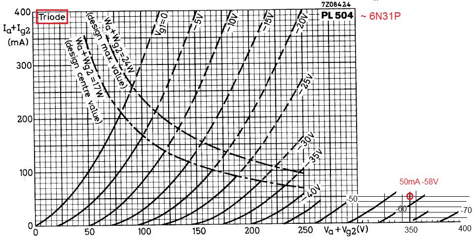
6N31P has 13 watt maximum anode+screen dissipation.
350V/50mA is quite a bit more.
It seems to be in the class of EL84 in terms of dissipation.
If you turn the current down = more -Vg1 = more drive voltage.That leaves less room for errors in the driver section.
Mona
Is 6P31S more like an PL504 or more like an EL37? They look different enough that it will matter.
6N2P is similar to US type 12AX7, Euro type ECC83.
6N6P is similar to US type 5687, Euro type E182CC (pretty much)
Uh oh. That tube does not look like it will be happy running at roughly 360V plate-cathode. I would use it cathode-biased, with a cathode bias resistor for each 6P31C, each bypassed by a suitable value capacitor. That way you could get the plate-cathode voltage down to about 320V or so. Even that is high for this tube, but should be more manageable.
It looks like max plate dissipation is about 12W, max screen dissipation is about 4W.
Max plate voltage is high, but the max screen voltage is 250V. My guess is that you might be able to push that to Vg2 = 300V.
If in triode mode, I'd treat this tube like a 2A3.
Vp-k = 250V
Ip+g2 = 60mA
Pdiss of p+g2 = 15W
Looking at page C in http://www.r-type.org/pdfs/el36.pdf, I think Vg would be about -20V or thereabouts. So each tube would need its own 330R to 390R cathode resistor (5W) bypassed by about 330uF.
These kinds of tubes are usually best used in pentode mode, with a regulated supply for the screens (g2). From what I understand of it, that's because their screen grids have very high transconductance, and so need to be run at lower voltages than 'audio' output pentodes like EL34, KT88, 6L6GC, etc.
--
I also have 6N2P , if one of those would be good in place of either 6N6P , maybe input/phase splitter . Dick van der Merwe opted for these in earlier iteration of MonoBill , but last iteration has 6N6P in both positions .
6N2P is similar to US type 12AX7, Euro type ECC83.
6N6P is similar to US type 5687, Euro type E182CC (pretty much)
6P31S ( or 6P31C ) is analogous to EL36 , not EL37 .
EL36 @ The Valve Museum
http://www.r-type.org/pdfs/el36.pdf
Uh oh. That tube does not look like it will be happy running at roughly 360V plate-cathode. I would use it cathode-biased, with a cathode bias resistor for each 6P31C, each bypassed by a suitable value capacitor. That way you could get the plate-cathode voltage down to about 320V or so. Even that is high for this tube, but should be more manageable.
It looks like max plate dissipation is about 12W, max screen dissipation is about 4W.
Max plate voltage is high, but the max screen voltage is 250V. My guess is that you might be able to push that to Vg2 = 300V.
If in triode mode, I'd treat this tube like a 2A3.
Vp-k = 250V
Ip+g2 = 60mA
Pdiss of p+g2 = 15W
Looking at page C in http://www.r-type.org/pdfs/el36.pdf, I think Vg would be about -20V or thereabouts. So each tube would need its own 330R to 390R cathode resistor (5W) bypassed by about 330uF.
These kinds of tubes are usually best used in pentode mode, with a regulated supply for the screens (g2). From what I understand of it, that's because their screen grids have very high transconductance, and so need to be run at lower voltages than 'audio' output pentodes like EL34, KT88, 6L6GC, etc.
--
Yes , earlier I was saying that I would want to go over 300V on the plate - this does seem " saner " . Perhaps even 250V .
EL36 operating in Class B PP
Va =300V
Vg2 = 150V
Vg1 = -29V
Raa = ~3,5k
Wo = 44,5W
Dist. = 7%
EL36 operating in Class B PP
Va =300V
Vg2 = 150V
Vg1 = -29V
Raa = ~3,5k
Wo = 44,5W
Dist. = 7%
To start with, best use the first schematic values.R22, R25 can stay 1k but I prefer 820 ohm, more linear.
The 6N31 is allmost an EL504 (PL504).If you see the bias voltage needed you understand why I proposed to modify the circuit from T-Dick.
Mona
Thanks for this Ketje !
And accordingly make :
Va = 300V
Vg2 = 300V
-50V G1 bias for 55ma
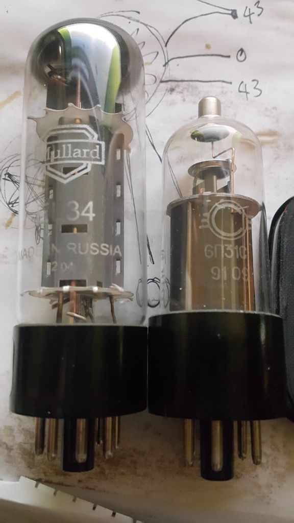
Aha, the Russian put the tube in a smaller bottle, I didn't now that.
The data, with exeption of the dissipation, are allmost the same with EL36/EL500/EL504.
Probably the anode extend down in the base and is bigger than it appears.
Look the PL36 is as big as the EL34.
Mona
The data, with exeption of the dissipation, are allmost the same with EL36/EL500/EL504.
Probably the anode extend down in the base and is bigger than it appears.
Look the PL36 is as big as the EL34.
Mona
Attachments

I fully agree with you Ketje - I did compare the EL36 vs EL504 , and they do appear to be virtually the same thing .
That begs the question -
B+ : 360 , 300 or 250V - what would you do ?
Haha - I just noticed I've got end of the " cold war " 6P31C's . 🙂
That begs the question -
B+ : 360 , 300 or 250V - what would you do ?
Haha - I just noticed I've got end of the " cold war " 6P31C's . 🙂
Last edited:
EL36 curves
Source : Index of /Yves

PP - Triode strapped :
http://www.dissident-audio.com/PP_EL36Triode/EL36-115.pdf
Source : Index of /Yves
PP - Triode strapped :
http://www.dissident-audio.com/PP_EL36Triode/EL36-115.pdf
Last edited:
Look at this interesting link on the EL36 : EL36: Applications in Audio
The EL34 is the best suited pentode to use in triode, but still no point of doing that. Believe me after a 2 hours warm up an EL34 tube in pentode is smoother than a 300B!
I am an ultra-linear addict, can't go back
The EL34 is the best suited pentode to use in triode, but still no point of doing that. Believe me after a 2 hours warm up an EL34 tube in pentode is smoother than a 300B!
I am an ultra-linear addict, can't go back
Last edited:
Time to warm them up then 😉
A possible config.
Mona
Looks good Ketje - thank you !
Look at this interesting link on the EL36 : EL36: Applications in Audio
The EL34 is the best suited pentode to use in triode, but still no point of doing that. Believe me after a 2 hours warm up an EL34 tube in pentode is smoother than a 300B!
I am an ultra-linear addict, can't go back
Good link ! Makes EL36 look rather promising ! I'll definitely also go UL . I'm posting Grant Wills's schematic here for interests sake .
Source : Grant Wills

Grant Wills -" I wanted to use them in ultralinear configuration and tying the screens at 1/2 supply did not permit this. The ratings indicate a maximum screen supply of +200V and so I hesitated to use the ultralinear mode. However, after trying several configurations which either oscillated, distorted or otherwise misbehaved, I tried them in ultralinear mode with a fairly high amount of bias (-50V), and they worked really well! They were by far the most linear of any valve I tried and worked well with a fairly low standing current (approx 25mA each) and put out the maximum power (17W)! This seemed to justify their rather high heater power requirement. So I don't know if it is okay to run these valves with such high screen voltages, but mine works really well.
(Max power of 17W was measured by applying a 1kHz sinewave to the amp and measuring the peak to peak voltage across an 8 Ohm dummy load at the point of clipping. The RMS volts = pp volts divided by 2.88 (twice the square root of 2). Power then = Vrms2/8 Ohm. Note that the max power will not be sustained at very low (30Hz) frequencies).
The power supply used an old Philips valve power transformer, which was up to the fairly high heater current load of (4 x 1.25A) + (3 x 0.3A) = 5.9A, and had a B+ winding of 110Vac which, when applied to a voltage doubler provided 300V B+. (The doubler generates twice 110 = 220Vac, which after full-wave rectification comes to roughly 220 x 1.414 which is a tad over 300Vdc).
I decided to use fixed-bias as it allows slightly higher anode-to-cathode voltage for the output valves than cathode bias. This requires a bias network with a negative voltage DC supply. But the technique you can see in the power supply section of the circuit, for also getting a negative voltage supply from a voltage doubler, is an old trick from guitar amplifier designs.
I added a 10 Ohm resistor in each 6CM5 cathode earth return to monitor cathode current (by Ohms Law the easily measured voltage across this resistor, divided by 10, yields the value of standing cathode current through the valve, this in turn being the sum of principally the anode current plus a lesser amount of screen current) and act as a fuse under overload conditions.
Note that the circuit doesn't have any provision for individual adjustment of output valve standing currents. This was because I used 4 Radiotron 6CM5's from the same batch with very similar characteristics. A couple of other 6CM5's that I tried varied a bit in standing current. It may be helpful to modify the bias supply with 4 x 50kOhm trimpots in parallel and then in series with an 82kOhm resistor to ground across the bias supply in place of the one 100kOhm trimpot. With each trimpot wiper independently feeding each output valve this arrangement could then provide individual bias control over each valve. If the bias voltage needs to be increased, the value of the 0.1µF capacitor feeding the bias rectifier can be increased.
The front end of the circuit is conventional. The Mullard 5-10 amplifier uses the same phase splitter as I have, and the text refers to it as "a cathode-coupled phase splitter". A footnote refers to an article in Wireless World May 1948 by W T Cocking entitled "Push Pull Input Circuits." It's a tried-and-true topology, recognised even in solid-state circuits as the "long-tailed-pair", and works well.
The S/N ratio for this amp was outstanding - maybe the C-core power transformer, or the star earthing, or the provision of a centre-tap on the heater winding, or my 100µF overkill filter capacitors on the small signal HT??? The noise and hum are just about inaudible listening directly to the drivers of my quite sensitive speakers - certainly better than other amp's I have used over the years, and pretty amazing for a valve amp! "
Last edited:
The EL34 is the best suited pentode to use in triode, but still no point of doing that. Believe me after a 2 hours warm up an EL34 tube in pentode is smoother than a 300B!
Do you live in an igloo?
Did you look at the dissident audio pdf Ketje ?
According to that I may go for : B+ 300V ; G1 -50V biased to 60mv
That is 18W for triode connected EL36 PP , so surely UL will provide more perhaps 40W with a little GNFB for 2 valves .
The EL34 vs EL36 comparison chart is very interesting ( compliments of gabdx ) : EL36: Applications in Audio
This makes me think that 70W PPP UL w a little GNFB may be possible with that Hammond 1650R . The comparison chart also leads me to believe that EL36 PPP RAA might be less than 2K ! Which will allow me to use 16ohm taps for 8ohm , and 8e for 4e . Right ?
That Wills thing is no good.You never get the 50Vtop to drive the finals from that phase splitter.And one bias for both tubes, bad idea.
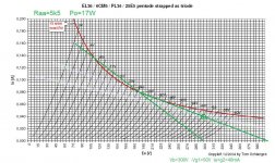
Oh, I forgot to say it, the loadline for Raa=5k5 is with one pair of tubes as triodes. PPP makes that 2k75 and dubble output power (~ 34W)
For UL on 300V , looks possible. The screen drops to around 170V at full power so we can use the 170V graphs.
Mona
Oh, I forgot to say it, the loadline for Raa=5k5 is with one pair of tubes as triodes. PPP makes that 2k75 and dubble output power (~ 34W)
For UL on 300V , looks possible. The screen drops to around 170V at full power so we can use the 170V graphs.
Mona
Last edited:
The power rating of the EL36 is (as any sweep tube) very conservative.
Taking the height of the anode as a rough indication, it should be able to take only a little less heat then EL34.
The 34 has an anode of 4cm high, the 36 measures 3cm. Comparable width, slightly slimmer bottle.
I'd say 18W shouldn't be an issue for this type.
In my living room amp there is over 400V on the anodes and regulated 150V on the screens. Cathode feedback winding on the OPT and just a little NFB.
Good sound, plenty of non-fatiguing power.
Works for me 🙂
Still have to see how they hold up in the long run but until now no problems.
Hi Parafeed .
Do you have a schematic to have a look at ? Just for comparative purposes . Or a link to your build ?
Do you have a schematic to have a look at ? Just for comparative purposes . Or a link to your build ?
That Wills thing is no good.You never get the 50Vtop to drive the finals from that phase splitter.And one bias for both tubes, bad idea.
Yes - I just liked what he was saying - still sticking to MonoBill front-end .
Oh, I forgot to say it, the loadline for Raa=5k5 is with one pair of tubes as triodes. PPP makes that 2k75 and dubble output power (~ 34W)
For UL on 300V , looks possible. The screen drops to around 170V at full power so we can use the 170V graphs.
Mona
Goodie ! 😀
Gonna make rev 3 of circuit now .
Last edited:
Well the screen voltage doesn't drop to 170V with 300V powersup.For that the tap has to be at 58% and a normal traffo does about 40% tap giving 210V lowest Vg2.
Never the less the graph for 170V gives a good idea, only a little to low.
Next problem is, you have no longer 360V for the driver.Has to be adapted to get 50Vtop out (in two directions)with a supply of say 280V (300 minus an R-C ripple att.)
Mona
Never the less the graph for 170V gives a good idea, only a little to low.
Next problem is, you have no longer 360V for the driver.Has to be adapted to get 50Vtop out (in two directions)with a supply of say 280V (300 minus an R-C ripple att.)
Mona
Attachments

- Status
- Not open for further replies.
- Home
- Amplifiers
- Tubes / Valves
- Classic 4 valve PPP circuits