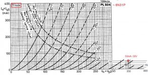
Those 6P31 data are for Vg2=170V ! Here, with UL, it's much higher and -50V is possibly even to little.
Quite correct. Still, there's plenty of gain available, even for up to 80V peak at the output tube grids. The phase splitter/driver stages are capable of 100X gain, open loop.
If you use the same V+ for both stages there is more risk of motorboating (feedback on the powerline).
Yes, totally agree. Decoupling (RC filtering) between power supply sections would definitely help, especially since there is this much gain available.
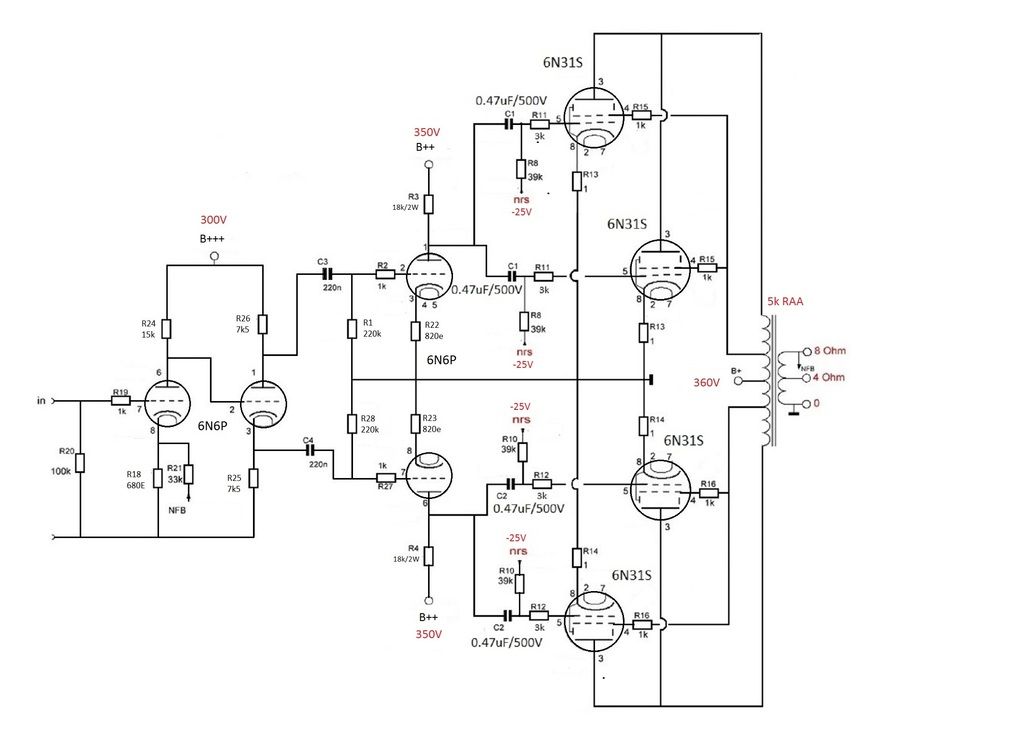
I'd suggest +360V to the output tubes/output transforme0r, +350V to the push-pull driver stage, and +300V to the input/phase splitter stage, with RC decoupling networks in the B+ between stages. To figure resistor values for the desired voltage drop, use good old Ohm's Law.
--
This is re-assuring . Somewhere else I was advised to get the get the voltage at the input stage anode ( after voltage drop resistor ) to between 85 and 95V . Can you see any sense in that ? Increased current ?
There is no magic plate voltage.
Generally speaking, a higher plate voltage will give you more possible voltage swing out from a triode, but again, there are balances to be struck at every turn.
Perhaps the person that suggested lowering the plate voltage to 95V was thinking of drawing 14mA or more through each 6N6P triode from that B++ supply (300V). But since the first two stages are DC coupled, you would then have to make sure the phase splitter is biased properly. Now you're redesigning that part of the amplifier.
The design process is more complicated than simply saying this voltage is better than that voltage and plugging that new number into a schematic. I could explain, but at this point you'd be better off buying a good textbook on the subject and figuring this out for yourself. Good books include Morgan Jones' "Valve Amplifiers" and Merlin Blencowe's "Designing High Fidelity Tube Preamps."
--
-50V bias does not seem to be correct for 6P31S; left from the other circuit?
Good catch indeed , I'll make updated schematic with proposed changes .
Good catch!! Yes, from looking at its data sheet (http://tubedata.milbert.com/sheets/113/6/6P31S.pdf) 6P31S with 360V on its plate would normally have about -25V grid-cathode bias.
Will update .
The proposed circuit should be fine if used with lesser output transformers and 10dB or less of NFB, in which case you need less gain than was used in the original circuit. Of course, if you use less NFB, you need to make sure the driver stages are more linear. Also, you'll wind up with a higher output impedance from your amplifier (lower damping factor) which will give you that 'tube-y' bass response (looser, less tight, possibly a slight bass boost).
Tubey bass response is exactly what I'm trying to avoid .
Every part of a circuit you 'improve' exacts a penalty on another part of the circuit's performance. The challenge of designing a good circuit is to strike a pleasing balance between all the various compromises. That makes it all too easy to fall into 'analysis paralysis.' (Ask me how I know...)
--
Let me make schematic with proposed changes and we take it from there .
Those 6P31 data are for Vg2=170V ! Here, with UL, it's much higher and -50V is possibly even to little.
This is what I make of it with some small changes.
If you use the same V+ for both stages there is more risk of motorboating (feedback on the powerline).
Mona
Thank you for your input Ketje . I just don't understand the 2 values in grey - 4m3 and 5m5 ?
There is no magic plate voltage.
Generally speaking, a higher plate voltage will give you more possible voltage swing out from a triode, but again, there are balances to be struck at every turn.
Perhaps the person that suggested lowering the plate voltage to 95V was thinking of drawing 14mA or more through each 6N6P triode from that B++ supply (300V). But since the first two stages are DC coupled, you would then have to make sure the phase splitter is biased properly. Now you're redesigning that part of the amplifier.
The design process is more complicated than simply saying this voltage is better than that voltage and plugging that new number into a schematic. I could explain, but at this point you'd be better off buying a good textbook on the subject and figuring this out for yourself. Good books include Morgan Jones' "Valve Amplifiers" and Merlin Blencowe's "Designing High Fidelity Tube Preamps."
--
I'll be sure to check out those books rongon .
See updated schematic with changes :
B++ : 360V to 350V
R24 : 47k to 15k
R26 : 18k to 7k5
R18 : 1k to 680e
R22/23 : 1k to 820
The G1 coupling capacitors are going to have to stay the same , I already halved the values from the original circuit , and I have enough of the 0.47 uF caps ( I did ask for 0.22uF's yesterday , but there was no stock ) .

That's the current, 4m3 = 4,3mA and 5m5 yes, 5,5mA
Mona
Aah ! I thought it might be , just wasn't sure , thank you , check out the revised schematic above and let me know what you think .
Cheers
Ari
Looking once more at the circuit, I would advice to take a look at a Mullard 5/20 style input/driver stage as maybe a better alternative.
Pro: less prone to unstability, therefore likely easier to mess around with gNFB.
Also a bit less open loop gain which is good for the output stage not asking that much voltage swing.
Pro: less prone to unstability, therefore likely easier to mess around with gNFB.
Also a bit less open loop gain which is good for the output stage not asking that much voltage swing.
fredeb, good to see you getting going on this. I don't have any knowledge of the tubes you are using so can't be of much help here. Hopefully the circuit is tailored to the tubes you are actually using and your knowledge of them.
I think it would definitely benefit you, or anyone else, to learn LTspice. Sure it is not 100% accurate because it is only as good as tube spice model, but it is amazingly helpful. There are things I've found using spice that I would not have found any other way except after it is too late and all the parts are ordered and the circuit did not work the way I expected. So I would consider taking a break and learning LTspice so you can input your circuit into it. It is a very good antidote to the bandwagon effect that so often happens. I'm not excluding that kind of influence to myself here. The only thing it really doesn't do is tell you how a circuit will sound. But the best thing it does when I'm thinking about a circuit is it keeps me honest.😀
I think it would definitely benefit you, or anyone else, to learn LTspice. Sure it is not 100% accurate because it is only as good as tube spice model, but it is amazingly helpful. There are things I've found using spice that I would not have found any other way except after it is too late and all the parts are ordered and the circuit did not work the way I expected. So I would consider taking a break and learning LTspice so you can input your circuit into it. It is a very good antidote to the bandwagon effect that so often happens. I'm not excluding that kind of influence to myself here. The only thing it really doesn't do is tell you how a circuit will sound. But the best thing it does when I'm thinking about a circuit is it keeps me honest.😀
The design process is more complicated than simply saying this voltage is better than that voltage and plugging that new number into a schematic. I could explain, but at this point you'd be better off buying a good textbook on the subject and figuring this out for yourself. Good books include Morgan Jones' "Valve Amplifiers" and Merlin Blencowe's "Designing High Fidelity Tube Preamps."
--
This is a much better approach IMO.
LTspice is a tool; you need the basic knowledge to use it in a useful way.
The books mentioned above will provide you with the basic knowledge, and once you master the (not so difficult to grasp) basic tube circuits there will be a lot more fun in building.
R25 and R26 should be equal in value.
Slowly, but we will get somewhere.
Thanks Pieter - updated .
This is a much better approach IMO.
LTspice is a tool; you need the basic knowledge to use it in a useful way.
The books mentioned above will provide you with the basic knowledge, and once you master the (not so difficult to grasp) basic tube circuits there will be a lot more fun in building.
Are you a part of the Hypex team Pieter ?
Looking once more at the circuit, I would advice to take a look at a Mullard 5/20 style input/driver stage as maybe a better alternative.
Pro: less prone to unstability, therefore likely easier to mess around with gNFB.
Also a bit less open loop gain which is good for the output stage not asking that much voltage swing.
But higher distortion, if using the same tubes at similar operation points.
The Williamson topology has higher gain with lower distortion, but is more prone to instability.
The Mullard topology has lower gain, higher distortion, but is more stable (due to lower gain and one less stage).
Compromises, compromises... always compromises.
--
PS - And once again, we end up here:
http://www.lundahl.se/wp-content/uploads/datasheets/amplifier_30wpp.pdf
That's a nice article for getting introduced to amplifier design. You could just build that and it would be very good.
--
Last edited:
Are you a part of the Hypex team Pieter ?
No!
Hypex company is within 2 miles from my doorstep and I know some of the guys, but I am into transformers 🙂
I'm not familiar with 6N31S. How similar is that to EL37?
http://tubedata.milbert.com/sheets/154/e/EL37.pdf
If similar, then it shows a push-pull arrangement for 350V plate-cathode and screen-cathode, with Vg at -31V.
--
http://tubedata.milbert.com/sheets/154/e/EL37.pdf
If similar, then it shows a push-pull arrangement for 350V plate-cathode and screen-cathode, with Vg at -31V.
--
Last edited:
PS - And once again, we end up here:
http://www.lundahl.se/wp-content/uploads/datasheets/amplifier_30wpp.pdf
That's a nice article for getting introduced to amplifier design. You could just build that and it would be very good.
--
Agree, Mullard style (which seems have to have the edge over Williamson style in terms of sound quality).
Could be done with 6N6P tubes as well (don't like current poor ECC83 when parallelled output tubes need to be driven).
Last edited by a moderator:
I've built a PP 2A3 amp using Mullard topology using 6DJ8 into a 6SN7 LTP, and a PP 2A3 amp using Williamson topology.
Between those two, I prefer the cleaner sound of the Williamson driver. But I did do it in two boxes, with the first two stages as a stand-alone preamp with balanced outputs (6SN7 with 6DJ8 phase splitter), and the last two stages as a power amp with very little gain (6N6P LTP and PP 2A3s). Because each box has its own power supply, there's no motorboating.
However, I can provoke motorboating between the last two stages with inadequate decoupling. But that's not an indictment of the Williamson topology. That's just my own mistake for not filtering the B+ to the last two stages well enough.
--
Last edited:
Looking once more at the circuit, I would advice to take a look at a Mullard 5/20 style input/driver stage as maybe a better alternative.
Pro: less prone to unstability, therefore likely easier to mess around with gNFB.
Also a bit less open loop gain which is good for the output stage not asking that much voltage swing.
But higher distortion, if using the same tubes at similar operation points.
The Williamson topology has higher gain with lower distortion, but is more prone to instability.
The Mullard topology has lower gain, higher distortion, but is more stable (due to lower gain and one less stage).
Compromises, compromises... always compromises.
--
PS - And once again, we end up here:
http://www.lundahl.se/wp-content/uploads/datasheets/amplifier_30wpp.pdf
That's a nice article for getting introduced to amplifier design. You could just build that and it would be very good.
--
I just going to stick to the decided topology now , lest I never get anywhere with it . Do you prefer the 1st or 2nd schematic ? 🙂 Do you think either are a good starting point ? Can be changed later , will build on a plank at first , and just 1 channel , with 2nd channel to follow when satisfied .
No!
Hypex company is within 2 miles from my doorstep and I know some of the guys, but I am into transformers 🙂
I'm going to PM you shortly .
- Status
- Not open for further replies.
- Home
- Amplifiers
- Tubes / Valves
- Classic 4 valve PPP circuits