Apex D200 V2 ,,,
Hi QQ12e5k1,
Looks like the component side is not matching,, Pls check the PCB.
Thanks
Hi QQ12e5k1,
Looks like the component side is not matching,, Pls check the PCB.
Thanks
Attachments
Last edited:
Hi QQ12e5k1,
Looks like the component side is not matching,, Pls check the PCB.
Thanks
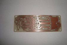
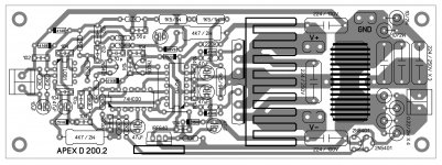
I give You complete layout include the mirror bottom side and You can match with component side before print it. But You print unmirror bottom side.
Apex D200.2 !!!
Mr.Mile,
Please find the amp assembled with Irf640n,Later will change with IRFB4227 ,,😉 will test initially with +/-45v ,
I would like to work this amp with +/-75v for subwoofer.😀
output is 30.5 uh with T157-2,
Mr.Mile,
Please find the amp assembled with Irf640n,Later will change with IRFB4227 ,,😉 will test initially with +/-45v ,
I would like to work this amp with +/-75v for subwoofer.😀
output is 30.5 uh with T157-2,
Attachments
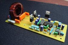
Mr.Mile,
Please find the amp assembled with Irf640n,Later will change with IRFB4227 ,,😉 will test initially with +/-45v ,
I would like to work this amp with +/-75v for subwoofer.😀
output is 30.5 uh with T157-2,
Nice work, replace IRF640N with TIP31C in 12V bias circuit. D200 can work with +/-75V rail.
Regards
Mr.Mile,
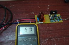
just checked with +/-48v I am getting Dc offset of 6.5v,😱 what could be the problem.
I am using BD241c in Bias ckt
just checked with +/-48v I am getting Dc offset of 6.5v,😱 what could be the problem.
I am using BD241c in Bias ckt
Last edited:
Mr.Mile,
just checked with +/-48v I am getting Dc offset of 6.5v,😱 what could be the problem.
I am using BD241c in Bias ckt
Load on amp output must be connected.
Hi Apexaudio 🙂
I can't find the final Schematic of your D200.2
So can you post the final Schematic and Layout again at here .
Thanks you so much .
I can't find the final Schematic of your D200.2
So can you post the final Schematic and Layout again at here .
Thanks you so much .
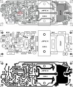
i've redraw the PCB for my heatsink and i thinks it not bad
But i don't have any Schematic of this , so may i had some mistake , please check for any problem on my PCB.
I still looking for the final schematic of this amp , please post this here , thanks so much .
Regards
But i don't have any Schematic of this , so may i had some mistake , please check for any problem on my PCB.
I still looking for the final schematic of this amp , please post this here , thanks so much .
Regards
Attachments
Hi all, I see a lot of versions. Which is the most recent version of the PCB? and another question, how many volts supply voltage up to be? And how we can get the maximum wattage is sound? Do not open the circuit diagram? Thank you very much.
Regards
Regards
Mr.Mile
Finally my amp worked,😀,, The problem was 74Hc00 pin 9,10,11 was not shorted in the PCB.
There was quite a Distorted O/P,,
Had replaced bias ckt with IRF640n and 15v zener, Then upon changing back to BD241 with 12v zener sound was clean without distortion.
Have replaced the mosfets with IRFB4227, the -ve side Mosfet warms up quite a bit, the other Mosfet is cooler,,,😕, is this normal,,
power supply checked with +/- 48v.
Attachments
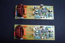
Mr.Mile
Finally my amp worked,😀,, The problem was 74Hc00 pin 9,10,11 was not shorted in the PCB.
There was quite a Distorted O/P,,
Had replaced bias ckt with IRF640n and 15v zener, Then upon changing back to BD241 with 12v zener sound was clean without distortion.
Have replaced the mosfets with IRFB4227, the -ve side Mosfet warms up quite a bit, the other Mosfet is cooler,,,😕, is this normal,,
power supply checked with +/- 48v.
Thank You Arasuk. I'm sorry, that's my mistake.
hi thienchay have you managed to test your design? pls post pcb files
This my last version PCB , i've added some capacitor in power supply port, and more space for more capacitor in output , i think more capacitor parallel is better , and easy for find .
This my PDF file , print 100% in A4 .
Thanks .
Regards 🙂
Attachments

Mr.Mile
Have replaced the mosfets with IRFB4227, the -ve side Mosfet warms up quite a bit, the other Mosfet is cooler,,,😕, is this normal,,
power supply checked with +/- 48v.
It isn't normal... use IRF640N instead IRFB4227 with +/-48V rails.
Regards
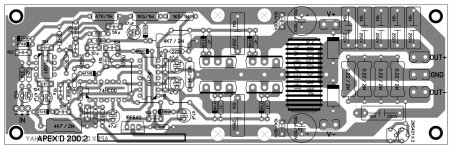
from suggested of Mr.Arasuk 🙂 , i've redraw this amp for more power and 2 ohm load , i call it is Apex D200.2 Turbo 😀 .
Regards
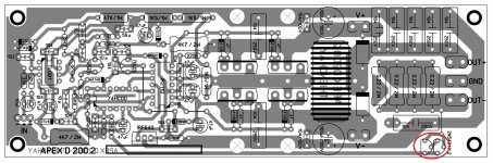
Nice work, but there is mistake.
Attachments
- Home
- Amplifiers
- Class D
- Class D Amp with LM566, LM393 and 2XIRF530