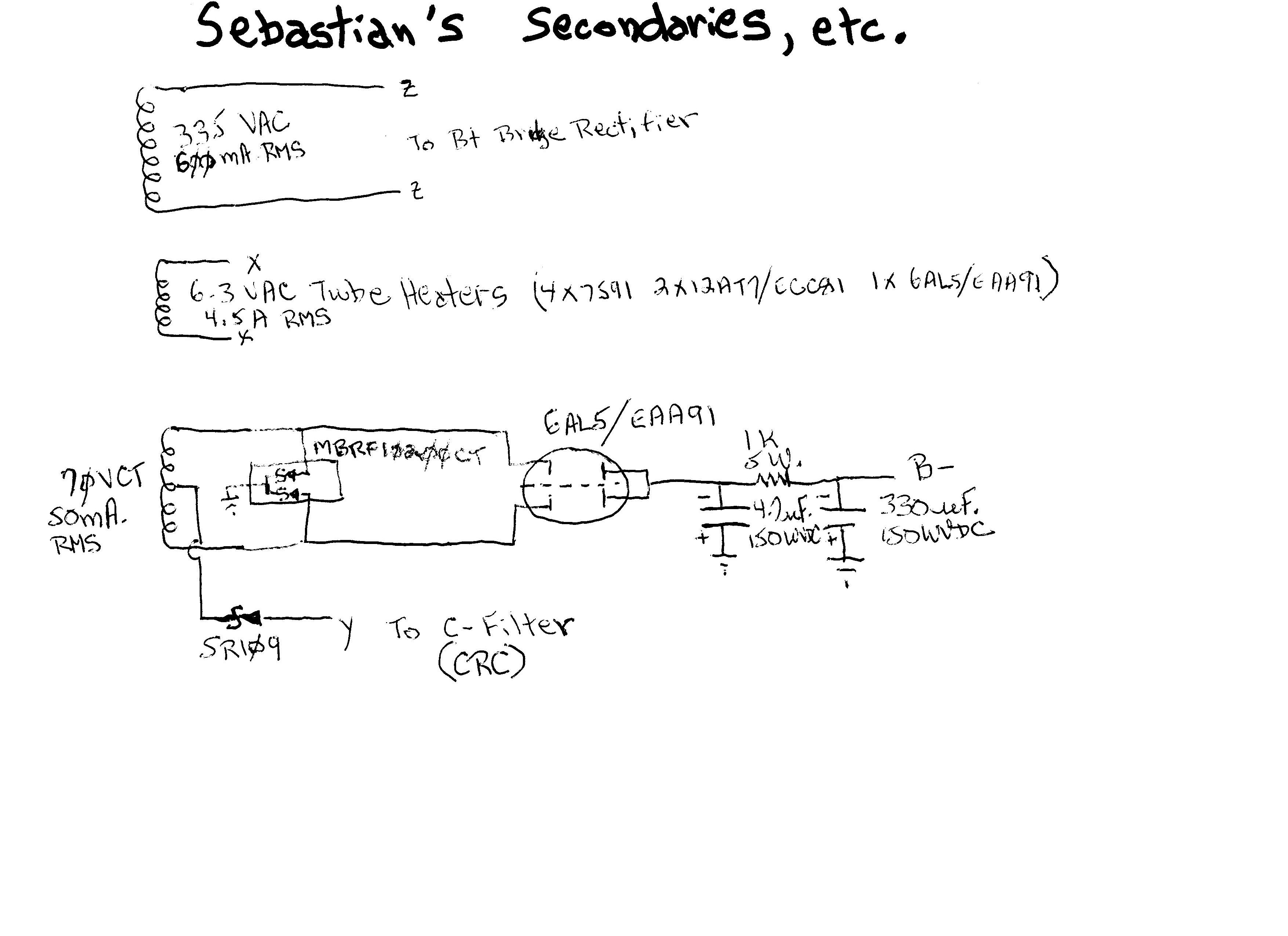
What is the voltage of the third secondary on that custom power transformer? That's the center tapped secondary for the B- and C- supplies.
It is 70V CT 50mA RMS
It is 70V CT 50mA RMS
OK, thanks. So...
What DC voltage do you expect to see at B- ?
What DC voltage do you expect to see at C- ?
What is the DCR of L1? (You'll need to know that to predict what the DC voltage at B+1 and B+2 will be.)
--
All I can tell you is what voltages I would expect to see, based on the tubes you'll be using.
The 305V AC secondary should yield about 420V DC right after rectification. The reason I asked about the winding resistance of the choke is that voltage will be dropped across that resistance. Maybe the winding resistance is 60 ohms and the four 7591's draw 50mA each. That would mean 0.2A x 60 ohms = 12V DC dropped across the choke. So now we're down to about 410V at B+.
Next, there's a 100 ohm resistor for each of B+1 and B+2, each with about 100mA going through it. That means 100 ohms x 0.1A or another 10V dropped, so now we're down to 400V DC for both B+1 and B+2.
Remember that these are just estimates. I often find that the final voltages differ quite a bit, depending on your wall voltage and the characteristics of your transformer.
So that's all pretty straightforward. Now, the 70V CT secondary gets the interesting stuff.
The B- supply is derived from a full wave bridge, with the negative voltage coming from the 6AL5 dual-diode rectifier tube, and the positive end going to ground through the fancy double-diode MBRF10200. I figure the raw voltage after the rectifiers should be about 70V x 1.414 - losses = roughly -95V DC. But I could be wrong about that.
What's got me a bit puzzled is how the C- supply works. It's half-wave rectified from the center tap of the 70V CT winding. Pretty cool that you can do that. I just don't know how to figure what voltage you'll get from that arrangement. Would that be 35V AC half-wave rectified through the SR109 diode? If yes, then expect about -45V DC or so for C-.
--
Last edited:
Ron,
The 2 rails from 1 CT winding idea comes from Pete Millett. Both rails are full wave rectified. The "short" rail is a FWCT setup. 😉 The diode connected to the CT is theoretically unnecessary, but provides insurance against an accident. Ignoring losses, the "tall" rail will 2X the "short" rail.
The exact voltage the 2 negative rails come in at is not critical, as long as they are not too low. The B- supply has to be "tall" enough to operate the CCS and provide the LTP with I/P signal compliance. Any extra volts get "eaten" by the CCS. The C- supply has to be able to control O/P tube "idle" current. Again, a bit too much is OK. The bias set trim pots. are there exactly for that reason.
Please refer to the 7591 data sheet. With 400 V. on the plate and 40 mA. of "idle" current per tube, a "fixed" bias UL mode PP pair yields 32 W. Wherever the B+ rail comes in, adjust the "idle" current to keep plate dissipation under the max. allowable 19 W. The example dissipates 16 W./tube.
Thanks Eli, that 2 rails from one CT winding trick is pretty slick. I'll have to try that one sometime.
Sebastian, I think you have your answer.
--
Sebastian, I think you have your answer.
--
Yeah, thanks Rongon!
So what you say Eli, can I just start prototyping the PSU, with the current schematic?
So what you say Eli, can I just start prototyping the PSU, with the current schematic?
Yeah, thanks Rongon!
So what you say Eli, can I just start prototyping the PSU, with the current schematic?
Not yet, sorry. Both negative rails take simple CRC filtration. Go back to my "hen scratches" and remarks. There's no need to spend more than necessary in getting the job done well.

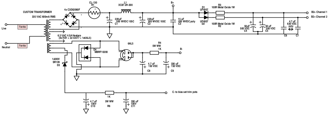
The C- filter needs to be corrected. Go back to earlier schematic iterations. The C- filter reservoir cap. is a Nichicon KZ.
C11 is redundant and should be eliminated. The value of C10 is too small. SS diodes are not subject to the limits of vacuum diodes. Use 100 or 150 muF. Only a few mA. get drawn from the C- supply.
BTW, the diodes inside a MBRF10200 are Schottkys.
BTW, the diodes inside a MBRF10200 are Schottkys.
Eli, just one more question:
Isn't that a problem that the choke is rated 2H at 300 mA? just because I am still searching for a hammond choke rated at the same specs, and stumbled upon that the transformer is 600 mA.
maybe this one can replace the edcor choke?
http://hu.mouser.com/ProductDetail/...=sGAEpiMZZMsVJzu5wKIZCZK62KAI4I1sz9ENb3satpo=
Last edited:
Also, there is no 50 uF 500 VDC capacitors on the market, just 50 uF 450 VDC caps.
Can I use the 450 VDC ones too?
Or wait... I have found this: http://www.tube-town.net/ttstore/Capacitors/F-T-Capacitors/F-T-50-50-F-500-V-Multisection::4407.html
Can I use the 450 VDC ones too?
Or wait... I have found this: http://www.tube-town.net/ttstore/Capacitors/F-T-Capacitors/F-T-50-50-F-500-V-Multisection::4407.html
Last edited:
VTA 70
If $1000 or slightly less is in your range I would seriously consider the VTA 70 which is an upgraded ST-70. I built one last year and i'm very happy with it.
tube4hifi ST70 page
If $1000 or slightly less is in your range I would seriously consider the VTA 70 which is an upgraded ST-70. I built one last year and i'm very happy with it.
tube4hifi ST70 page
Also, there is no 50 uF 500 VDC capacitors on the market, just 50 uF 450 VDC caps.
Can I use the 450 VDC ones too?
Or wait... I have found this: F+T 50 + 50 µF / 500 V Multisection - Tube-Town GmbH
You don't need exactly 50uF. 47uF, 56uF, 68uF would be fine. 33uF is probably fine too (I think).
You need the C1, C2, C4 and C5 power supply capacitors to be rated for a higher voltage than they'll actually see in regular use, since there will be voltage surges at turn on, etc. That's why the 500V DC rating.
If you really can't find any 500V DC rated capacitors, it is possible to series connect two capacitors to make the equivalent of a single, higher voltage capacitor. Current-sharing resistors are mandatory. Are you familiar with this?

Capacitors in Series
--
Last edited:
- Home
- Amplifiers
- Tubes / Valves
- Choosing a tube amplifier to build, HELP needed