Rongon is right. That impedance plot is fugly. 😡 The dips at "50" and "170" Hz. are of considerable concern. The 3 peaks are also problematic.
A constantly moving target is quite bothersome.
As custom O/P transformers are going to be wound, things might work out. The winder will have to make the secondary impedance 3 ohms. Be aware that money could be spent, without getting a return.
Frankly, the new speakers should be mated to good SS power amplification. The Tannoy speakers were more or less manageable. All bets are off, given the new stuff's nasty impedance plot.
I still can change it back! 🙂 So if you guys say that the Tannoys would be better, I'll change it back, it did not have such a big difference anyways! 🙂
I take it back tomorrow and change it back 🙂
So Let's revert! I stay with the Tannoys! 🙂
Thanks for the feedbacks, and thank you Rongon! I can understand all the things 🙂
I take it back tomorrow and change it back 🙂
So Let's revert! I stay with the Tannoys! 🙂
Thanks for the feedbacks, and thank you Rongon! I can understand all the things 🙂
Last edited:
Older Tannoy speakers were generally easy-ish loads for tube amps to drive, but I have no idea how current Tannoy speakers are in this regard. You'd need to see the impedance curve to know for sure.
I looked up your Tannoy speakers, and there is no impedance curve available that I can find.
As for whether the one speaker will sound better than the other, well, that's up to you. Speakers are all quite imperfect. Which speaker you'll like better than another is often a matter of taste, not of one being 'better' than another. And since modern-day speakers are not designed with tube amps in mind, that throws everything into chaos.
I'm sorry there are no clear-cut answers for you. That's just the way things are.
--
I still can change it back! 🙂 So if you guys say that the Tannoys would be better, I'll change it back, it did not have such a big difference anyways! 🙂
I take it back tomorrow and change it back 🙂
So Let's revert! I stay with the Tannoys! 🙂
Thanks for the feedbacks, and thank you Rongon! I can understand all the things 🙂
Sebastian, definitely get the Tannoy speakers back.
 Their impedance curve is much less problematic.
Rongon, go back towards the beginning of this thread. Sebastian got a hold of and uploaded the Tannoy speakers impedance curve. While not problem free, they are not downright hostile to tubed power amplifiers. You also mentioned having a Scott 7591 integrated in sad shape. Other than having to chose between full pentode and triode modes, there is no reason you can't repurpose those magnetics into a "Grande" build. 😉
Rongon... You also mentioned having a Scott 7591 integrated in sad shape. Other than having to chose between full pentode and triode modes, there is no reason you can't repurpose those magnetics into a "Grande" build. 😉
Yes, that is a definite possibility!
I also have the gutted chassis and iron of an Eico ST40 to work with. I actually need to get that working for someone, so it might be good for this project. The system it will go in won't have a preamp with gain, so it needs to be driven to full power with only 1V RMS input (sources are iPhone, CD player, standalone RIAA preamp). Would a pentode 7591 El Cheapo Grande with gNFB have that sensitivity?
Also, how is 7591 in triode? I've never tried that. I don't generally like 6L6GC in triode, but EL34-triode sounds OK to me. I wonder how 7591-triode compares...
Do you think 10 watts per channel is achievable with PP 7591-triode?
--
more info:
It looks like with a GZ34 rectifier, the Eico ST40 B+ should be just about 400V. In the original manual, the 7591's are set to draw 56mA each at idle, which is a pretty whopping 224mA. All the rest of the tubes in the amp are 12AX7 or 12DW7, so are low current draw types. I guess the power transformer is good for 230mA minimum. The sheet shows the AC at the GZ34 is 335VAC x2, so 670VCT. This is great!
The original circuit is rated for 20 watts per channel. I guess the OPT's are rated for no more than about 35W each, right? They are kind of small...
--
Last edited:
Also, how is 7591 in triode? I've never tried that. I don't generally like 6L6GC in triode, but EL34-triode sounds OK to me. I wonder how 7591-triode compares...
I think you will like triode mode 7591s more than similarly wired 6L6s.
I also have the gutted chassis and iron of an Eico ST40 to work with. I actually need to get that working for someone, so it might be good for this project. The system it will go in won't have a preamp with gain, so it needs to be driven to full power with only 1V RMS input (sources are iPhone, CD player, standalone RIAA preamp). Would a pentode 7591 El Cheapo Grande with gNFB have that sensitivity?
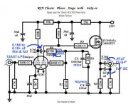
This particular implementation requires maximizing open loop gain and reducing the % of the O/P voltage fed back. "Borrow" the dc coupled ZVN0545A source follower from the tweaked RCA phono preamp and use it to isolate the splitter/driver from the "finals". That will increase the net AC load impedance and stage gain. Adding the buffering FETs allows pure "fixed" bias to be employed. Making the 7591 grid to ground resistance a very safe 100 Kohms is perfectly feasible.
Do you think 10 watts per channel is achievable with PP 7591-triode?
If we can get 30+ WPC in UL, 10 WPC in triode should be very easy.
Use 2X Cree C4D02120A Schottky diodes to rectify the B+. Voltage multiply the 5 VAC winding to obtain the requisite negative voltages.
Attachments
How much drain current should the ZVN0545A draw? If driving a trioded 7591, it should be at least 3 or 4 milliamps, no? I figure Miller capacitance at the grid plus strays could add up to a possible 200pF. Probably less, but it's better to be safe.
The ZVN0545A is a nice part that even wimpy tubes, like the 12AX7 and EF86, have no problem driving. However, both voltage and power handling capabilities are limited. As the 12AT7/ECC81 is not a wimp, let's switch to the IRFBC20. The bigger FET is reasonably easy to drive, exhibits a crucial small reverse transfer capacitance, and provides the "stones" needed. A 5 mA. drain current rates to be "a piece of cake".
BTW, experience has shown that a protective Zener diode needs to be connected between gate and source. Voltages are "sideways", until the tube starts conducting. Use a 12 V. Zener with the ZVN0545A and a 15 V. part with the IRFBC20.
BTW, experience has shown that a protective Zener diode needs to be connected between gate and source. Voltages are "sideways", until the tube starts conducting. Use a 12 V. Zener with the ZVN0545A and a 15 V. part with the IRFBC20.
Last edited:
OK, sounds good. I might have some IRF820 in the stash. I'll have to see when I get home.
One other question.. With UF4007 diodes, I expect the B+ from this power transformer to be about 430V or so. Assuming 430V on the 7591 plates, that means the 7591 bias voltage will be somewhere around -25V (410V or so plate-cathode on the 7591's). Can a 12AT7 LTP swing that many volts cleanly? I once measured a 12AT7 LTP that had 100k plate resistors and an LM317 CCS in its tail. I got 24X gain from it. This makes me worry that a 12AT7's voltage swing capabilities might be a bit marginal here.
Maybe it would be better to use a 5U4GB or 5R4GY rectifier to drop about 40V at 225mA, which would bring the rectified voltage down to right about 390V, so 7591 plate-cathode would be roughly 370V, bringing the required swing from the 12AT7 LTP down to under 20V peak. Still, that would leave no room for NFB.
Am I looking at this right?
Added later -- I can see why the original circuit used 12DW7. That's the equivalent of a 12AX7 voltage amp into a 12AU7 split-load phase inverter. The roughly 50X achievable gain from the 12AX7 section is enough for a bit more than -6dB NFB. Right?
--
Last edited:
I once measured a 12AT7 LTP that had 100k plate resistors and an LM317 CCS in its tail. I got 24X gain from it. This makes me worry that a 12AT7's voltage swing capabilities might be a bit marginal here.
You have probably overlooked the next stage grid to ground resistance. The net load presented to the 'T7 is the parallel combination of the 100 Kohm part and the grid to ground part. Theoretical max. gain is 30X. With the buffering FET, I make the gain to be approx. 26X. That's tight, but adequate.
Please keep in mind that "El Cheapo" projects the 2 VRMS signal of a "standard" CDP as the source. The 1 VRMS from atypical sources is a bit of a "curve ball".
We could rearrange the gain structure to add a no NFB 12B4 voltage amplifier, at the I/P and switch to a 6J6 operated with the same parameters as the 'T7 in the LTP position. "Ditch" the FET buffers and go back to combination biased "finals". BTW, you get to use 100 Kohm controls, with this iteration.
Hi Rongon
I have a triode wired 7591 El Cheapo. I'm very happy with the sound but gain and power are marginal. With about 400V B+, combination bias and allowing for the voltage drop across the primary winding, it will do about 8 watts on a good day. The Sylvania datasheet has triode curves if want to take a look.
I have a modest amount of global NFB, but needs about 2V rms for full power. From memory the gain of the LTP is about 17 with 62k anode loads and 270k grid resistors for the 7591's. Gain could be improved using a Mosfet driver but I doubt you could achieve 1V sensitivity. I'm driving mine from an active crossover so I have plenty of gain available there.
I'm actually thinking of converting to Pentode using the output transformer secondaries for cathode feedback (I don't have ultralinear tappings). This will require much more gain in the driver to allow a decent amount of NFB so a complete redesign will be necessary. But power will increase from 8 watts to 30 watts!
Hmmm.... Well, that's the fun of these things. Compromises to be made, everywhere you look.
Yes, I see what you mean. Maybe the iPhone requirement can be dropped, and then it would all fall into place very nicely.
If a voltage amp stage has to go in front of the LTP, I'd use something kind of standard like a 6DJ8, then DC-couple that to a lower-gain but higher current LTP made of something like a 12BH7. That would be a variation on the ever-popular Mullard 5-20 style circuit, like in an Eico HF87, but scaled down in voltage and gain.
I don't have any 6J6, but that is an interesting looking tube. It just doesn't look very linear, though. The mu varies quite a lot with plate voltage/current changes.
http://www.mif.pg.gda.pl/homepages/frank/sheets/093/6/6J6.pdf
--
Please keep in mind that "El Cheapo" projects the 2 VRMS signal of a "standard" CDP as the source. The 1 VRMS from atypical sources is a bit of a "curve ball".
Yes, I see what you mean. Maybe the iPhone requirement can be dropped, and then it would all fall into place very nicely.
If a voltage amp stage has to go in front of the LTP, I'd use something kind of standard like a 6DJ8, then DC-couple that to a lower-gain but higher current LTP made of something like a 12BH7. That would be a variation on the ever-popular Mullard 5-20 style circuit, like in an Eico HF87, but scaled down in voltage and gain.
An externally hosted image should be here but it was not working when we last tested it.
I don't have any 6J6, but that is an interesting looking tube. It just doesn't look very linear, though. The mu varies quite a lot with plate voltage/current changes.
http://www.mif.pg.gda.pl/homepages/frank/sheets/093/6/6J6.pdf
--
Hi Rongon
I have a triode wired 7591 El Cheapo. I'm very happy with the sound but gain and power are marginal. With about 400V B+, combination bias and allowing for the voltage drop across the primary winding, it will do about 8 watts on a good day. The Sylvania datasheet has triode curves if want to take a look.
I have a modest amount of global NFB, but needs about 2V rms for full power. From memory the gain of the LTP is about 17 with 62k anode loads and 270k grid resistors for the 7591's. Gain could be improved using a Mosfet driver but I doubt you could achieve 1V sensitivity. I'm driving mine from an active crossover so I have plenty of gain available there.
I'm actually thinking of converting to Pentode using the output transformer secondaries for cathode feedback (I don't have ultralinear tappings). This will require much more gain in the driver to allow a decent amount of NFB so a complete redesign will be necessary. But power will increase from 8 watts to 30 watts!
Poindexter's "Musical Machine" provided considerable inspiration for "El Cheapo" Poinz originally used 5965 LTPs, but switched to 6GK5s later on. Between the 6GK5s higher mu and lower plate resistance vs. the 'T7, LTP stage gain will rise a fair amount. 6GK5s are inexpensive enough for you to buy several and cull out some matched pairs.
Thanks Eli, but I hate metalwork and don't want to punch another hole in the chassis so I am limited to a single dual triode or triode-pentode. I have a design using a CCS loaded triode DC coupled to a concertina phase splitter that sims quite well, I might start a new thread about it.
Hi Rongon
I have a triode wired 7591 El Cheapo. I'm very happy with the sound but gain and power are marginal. With about 400V B+, combination bias and allowing for the voltage drop across the primary winding, it will do about 8 watts on a good day. The Sylvania datasheet has triode curves if want to take a look.
I have a modest amount of global NFB, but needs about 2V rms for full power. From memory the gain of the LTP is about 17 with 62k anode loads and 270k grid resistors for the 7591's. Gain could be improved using a Mosfet driver but I doubt you could achieve 1V sensitivity. I'm driving mine from an active crossover so I have plenty of gain available there.
I'm actually thinking of converting to Pentode using the output transformer secondaries for cathode feedback (I don't have ultralinear tappings). This will require much more gain in the driver to allow a decent amount of NFB so a complete redesign will be necessary. But power will increase from 8 watts to 30 watts!
Thanks for weighing in tikiroo! Good info there. May I ask what output transformers you're using? (Mine don't have UL taps either.)
A solid 8 watts per channel would be OK. The person who will be using this doesn't plan to play his music very loud (mostly Americana, folk, blues, some jazz, not much rock). He's also picked up a pair of JBL 4311 studio monitors (and really likes them). I think those are quite easy to drive, 91dB/1W/1m, 8 ohms. His living room is kind of live, with mostly wood floors, some area rugs. He says he's looking for a 'warm and musical' sound from the amp, rather than for the lowest distortion/highest fidelity possible. My concern is that the amp should be very reliable, so plate dissipation ratings should be kept within reasonable limits. I'd also like to use easy-to-find tubes. 7591 is exotic by this standard, but not too bad now that Sovtek makes them. 6L6 and 12AT7 would be ideal, since they're popular types for guitar amps.
--
It's funny that we're back at the Big 3 of push-pull driver circuits -- voltage amp>cathodyne, Mullard-style, and high-mu long-tailed-pair. Then there's the LTP>push-pull driver, but we don't need that much gain, do we?
Last edited:
Transformers are vintage Partridge P3667 with a choice of 8k or 6k primaries and 2x3.75 ohm secondaries. Secondaries are in series for 15 ohm nominal impedance. I'm using the 8k primary, speaker impedance probably averages about 13ohm. Voltage at the 7591 anodes about 390V
I'd also like to use easy-to-find tubes. 7591 is exotic by this standard, but not too bad now that Sovtek makes them. 6L6 and 12AT7 would be ideal, since they're popular types for guitar amps.
The 6L6 requires lots more drive voltage than the 7591. The beauty of the 7591 is that it is as easy as "12" W. tubes to drive. The end to end impedance of 7591 O/P "iron" is correct for 6L6s, but the power handling is too low for 'GCs.
The 6L6 requires lots more drive voltage than the 7591. The beauty of the 7591 is that it is as easy as "12" W. tubes to drive. The end to end impedance of 7591 O/P "iron" is correct for 6L6s, but the power handling is too low for 'GCs.
Yes, I understand that 6L6 types require higher drive voltage (usually about 40 volts peak at their grids). Also, I was thinking smaller 6L6's, like Russian 6P3C (no "-E") or old 6L6GB.
I'm waiting to find out if the requirement for full volume from an iPhone can be gotten rid of. The CD player is standard, and the phono preamp can deliver the necessary 2V RMS out.
I'm working today, but will be able to dig out the amp and take voltages, hopefully this evening.
Assuming use of a 12AT7 as the driver for a pair of 7591, what is the advantage of the LTP over a voltage amp/split load inverter? I could get more gain out of the voltage amp/split load inverter than from the LTP...
tikiroo said:Transformers are vintage Partridge P3667 with a choice of 8k or 6k primaries and 2x3.75 ohm secondaries. Secondaries are in series for 15 ohm nominal impedance. I'm using the 8k primary, speaker impedance probably averages about 13ohm. Voltage at the 7591 anodes about 390V
Nice! I don't think the Eico OPT's are quite up to Partridge spec, but they're reputed to be pretty good.
--
Assuming use of a 12AT7 as the driver for a pair of 7591, what is the advantage of the LTP over a voltage amp/split load inverter? I could get more gain out of the voltage amp/split load inverter than from the LTP...
"Concertina" phase splitters are limited in their voltage swing capability. "El Cheapo" is a 2, not 3, stage setup. NFB is applied to a grid, instead of a cathode, and the loop is short. Perhaps the 2 stage topology sounds "better".
I'm not sure why the split-load (concertina) is limited in voltage swing in comparison to an LTP with *all things being equal* (available B+ volts, available plate current, etc.).
Say I have a 350V B+. I'm going to use a 12AT7.
Let's say the LTP will have 50k plate resistors. It will need a negative supply in order to get a large enough impedance in its tail. If we put a -25VDC supply and a 6mA CCS in the tail, that puts the voltage at the 12AT7 plates at 200V. Apply a 2.8V peak signal and gain of about 25X and we have a possible swing of 70V peak. That's plenty for driving a pair of 7591's with bias of -20V, and enough to drive a pair of EL34's with -35V bias, with just barely enough extra gain for 6dB of NFB (but zero headroom). It's not enough for a pair of 6L6 with -40V bias, if NFB is to be applied.
Looking at the split-load inverter: At the same 350V B+, and at the same 3mA per triode half of a 12AT7, we'll use a 50k plate resistor on the voltage amp stage, and a pair of 27k resistors for plate and cathode loads on the split-load stage. Again, the plate voltage at the voltage amp plate will be 200V. (We can cap-couple the first and second stages.) The split-load stage will have 81V dropped across each 27k load resistor, which leaves 188V plate-cathode.
If we again apply 2.8V signal to the input grid, and assuming an achievable gain of only 40X, we get 112V peak output.
So, how exactly is the split-load inverter 'limited in voltage swing capability' in a direct comparison to an LTP under the same conditions? Is the split-load stage limited to swinging the 81V dropped across its plate and cathode load resistors? Even so, we can get 81V peak swing from the above, which beats the LTP by 11V.
I had an idea. Why not use an input transformer to split phase, and then send the balanced signal to a 12AT7 differential stage? That way the non-inverting half is no longer getting its input signal from its cathode, so we get the full gain from each 12AT7 triode, no? (We can also lose the large impedance in the tail, which leaves more room for large voltage swings.)
https://www.edcorusa.com/xsm15k-15k
I've used a pair of these at the inputs of a push-pull 2A3 amp, and it sounds pretty good. I also tried the cheaper WSM15K-15K, but that one doesn't have the primary inductance necessary for deep bass response. Still, it was pretty OK, and sounded fine. I still have that pair of the smaller WSM version available...
--
Last edited:
- Home
- Amplifiers
- Tubes / Valves
- Choosing a tube amplifier to build, HELP needed