I might suggest adding one or two plastic snubbing capacitors to the pre-amp power supply at the PS output rails ... 0.1 to 1.0 uF MKS type (sprague or other) should do it.
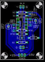
I think I already got that. There's a couple of plastic caps right after the regulators, between rail and ground. Later there's a 47uF electrolytic cap in parallell with a 100nF plasic just before the supplypins of the OP-amps. Since I etched the PCBs mirrorimaged I had to mount the OPs on the copperside while the other components are on the other.
Here's the layout.
The Freebird by Russ White
Attachments
kmj:
Yes, I see: 100 nF (0.1 uF) right there on your silk screen/board designations ... 😎
Looks like a very good board layout as well ... plenty of ground plane around the output, etc.
One might assume then that the hum is from an outside radiation source ... 😕
Yes, I see: 100 nF (0.1 uF) right there on your silk screen/board designations ... 😎
Looks like a very good board layout as well ... plenty of ground plane around the output, etc.
One might assume then that the hum is from an outside radiation source ... 😕
yes, probably 🙂One might assume then that the hum is from an outside radiation source ...
..hi to everybody..
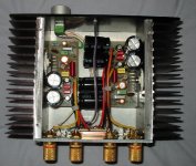
this wonderfull "chip amp" thread motivated me to use my scrap pile and assemble one to acompany a small woofer for my experimental esl's ..
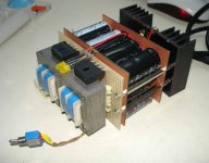
.. so i take the opportunity to present you my "sandwich" realisation..
all in one chassis-monoblock, transformers are doubled to get center tap from 17vac outputs and 220vac (2x110) input, rectifiers are doubled because i had them, capacitor bank is not that big as they are 470ìf/200v each from pc psu's x12, tda1514 is shelded from ps with unetched grounded boards ..
here is what i mean :
this wonderfull "chip amp" thread motivated me to use my scrap pile and assemble one to acompany a small woofer for my experimental esl's ..
.. so i take the opportunity to present you my "sandwich" realisation..
all in one chassis-monoblock, transformers are doubled to get center tap from 17vac outputs and 220vac (2x110) input, rectifiers are doubled because i had them, capacitor bank is not that big as they are 470ìf/200v each from pc psu's x12, tda1514 is shelded from ps with unetched grounded boards ..
here is what i mean :
Attachments

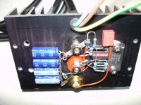
.. and a closer shot of the chips wires and parts..
this is the simplest of the datasheets application cirquit without the bootstrap .. i dont know if this is better or not, except for the comment of the datasheet saying i'll loose some 4 watts of output..
..if someone could explain in simple words the bootstrap effect on cirquirtry and audio quality i would appreciate it mucho..
Attachments
My First NIGC
Just sharing my first kit I got from Madaboutsound.
NIGC Monoblocks


I'll change the casing for the monoblocks if I find a better one
thanks for looking...🙂
Just sharing my first kit I got from Madaboutsound.
NIGC Monoblocks
I'll change the casing for the monoblocks if I find a better one
thanks for looking...🙂
Hi Audio Chippers
My first post.
I am very excited to have joined this wonderful community.
This is my first LM3875 based amp (hoping the photo uploaded) built in Jan 2003 before I had heard of GC or diyAudio, Parts and PCB are far from ideal but it sounds better than many Hi Fi amps I have auditioned.
PS is through the DB25, +/-42v. Also tried with +/-36v batteries but sounds much the same.
Have built 7 more amps with the LM3886 and another 3 using paralleled LM4780 the first in Aug 2003, They all sound much the same with just very subtle differences.
I have more photos if anyone is interested?
Just finished a paralleled LM4780 with regulated power supplies (+/- 38v), Sounds very warm and probably the best sounding amp so far.
Now working with the LM4702
Attachments
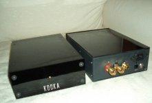
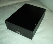
FastEddy said:Kooka: ... where did you get the cases??
That's a really fine lookin' outfit ...
I make them modifying a case made for DAC-ah.
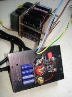
Kooka: Very clean! ... very sanitary ...
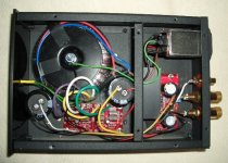
That power line moduler line filter = a nice touch, often overlooked and it works as you probably know ... likewise, the "bulkhead firewall" shielding the amp stage from the transformer & power supply & power switch (!!). (Also noticed: the common power / chassis ground connection is the center mount lug of your torrid transformer = good thinking = shielded from the amp at center of the major electro-magnetic field ... )
Good show!
Thanks guys for the nice comments.
What made a big difference after installing them are the 2 big extra capacitors on the supply. I am a newby in GC world, so nothing new to you all...
What made a big difference after installing them are the 2 big extra capacitors on the supply. I am a newby in GC world, so nothing new to you all...
FastEddy said:Those big caps are required for many, nah most amplifier power supplies ...

My english is not so good, so maybe I missed your point about this...
- Home
- Amplifiers
- Chip Amps
- Chip Amp Photo Gallery